15
Hardware Information
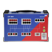
1.3 Functional Components of the CP SB1
The front panel of the CP SB1 provides the following functional components:
• Transformer High Voltage:
– Outputs (Source) for the input of current or voltage on the individual
phases of the transformer
– Inputs (Measure) for the voltage measurement
Note: The inputs and outputs of the respective connections (U/H1, V/H2,
W/H3, N/H0) are connected to the transformer using Kelvin clamps.
• Transformer Low Voltage:
– Outputs (Source) for the input of current or voltage on the individual
phases of the transformer
– Inputs (Measure) for the voltage measurement
Note: The inputs and outputs of the respective connections (u/X1, v/x2,
w/x3, n/X0) are connected to the transformer using Kelvin clamps.
• Tap Changer: Two potential-free contacts for switching the tap changer
• AC input for connection to the 2 KV AC output of the CPC 100
• DC input for connection to the 6 A DC output and I AC/DC input of the
CPC 100
• AC output for connection to the V1 AC input of the CPC 100
• DC output for connection to the V DC input of the CPC 100
• Serial interface for the CPC 100 (TRRatio and TRTapCheck test cards) to
control the CP SB1
• Equipotential ground terminal for grounding the CP SB1 close to the position
of the operating staff
 Loading...