63
Appendix
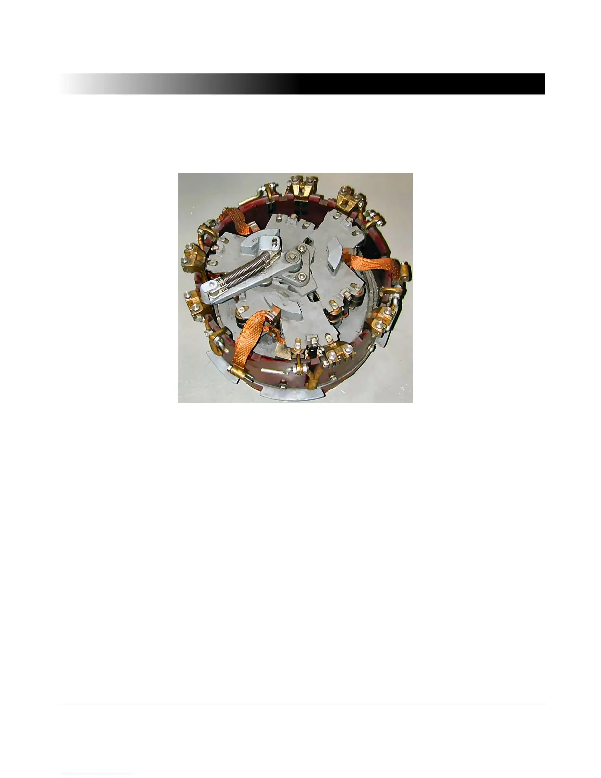
Figure 5-7 shows a diverter switch of a 40 MVA transformer for 110 kV. The
switches shown are positioned near the star-point of the transformer's high
voltage windings.
Figure 5-7 Diverter switch for 110 kV / 40 MVA
5.1.4 Four-Wire Connection for Transformer Winding Resistance
Measurement
Since the winding resistances are very small, the test set is connected in a four-
wire configuration. It has to be observed that the contact resistances of the
connection clamps do not falsify the measuring result.
A constant current source is used to feed a direct current into the winding. The
test current should be at least 1% of the rated current to bring the core into
saturation. On the other hand, it should not exceed 15% of the rated current to
avoid temperature rise during measurement. A relatively high no-load voltage
enables a quick saturation of the core and a final value with only minor
fluctuations is reached. Therefore, in most cases the charging time per tap is
distinctly less than 30 seconds.
 Loading...