3 Operation Procedure for DriveProgramming
3 - 6
DriveProgramming User’s Manual (I622-E1)
In the DriveProgramming, you can use the inverter's I/O functions (I/O terminal and analog I/O) as the
I/O functions of the program.
To use the I/O functions, it is necessary to set each I/O function according to the purpose.
This section describes how to set I/O functions for the DriveProgramming.
By configuring the following settings, you can control I/O functions by the function variables of the
DriveProgramming.
In the case that you use the functions for purpose other than DriveProgramming I/O functions, refer to
the High-function General-purpose Inverter 3G3RX2 Series User's Manual (I620).
Precautions for Correct Use
• For Input terminal 1 to 9, A and B, when MI1 to MI11 (General-purpose inputs 1 to 11) is
selected, Input terminal [1 to 9, A,B] active state (CA-21 to CA-31) is enabled.
• For Output terminal 11 to 15, relay output terminal 16 and relay output terminal AL selection,
when MO1 to MO7 (General-purpose output 1 to 7) is selected, Output terminal [11 to 15]
active state (CC-11 to CC-15), Output terminal [16] active state and Output terminal [AL]
active state (CC-16, CC-17) are enabled.
• In the DriveProgramming, the analog I/O functions are allocated to XA(0) to XA(2), and YA(0)
to YA(2). You can monitor the analog I/O status in the programs by using these function vari-
ables regardless of the settings for A101, Cd-03 to Cd-05.
• When MI1 to MI11 (General purpose inputs 1 to 11) is not set for Input terminal [1 to 9, A B]
function on the program for DriveProgramming, states of the input signal cannot be moni-
tored. Also, when MO1 to MO7 (General purpose outputs 1 to 7) is not set for Output terminal
[11 to 15] function and Relay output terminal [16, AL] function on the program for DrivePro-
gramming, states of the output signal cannot be monitored.
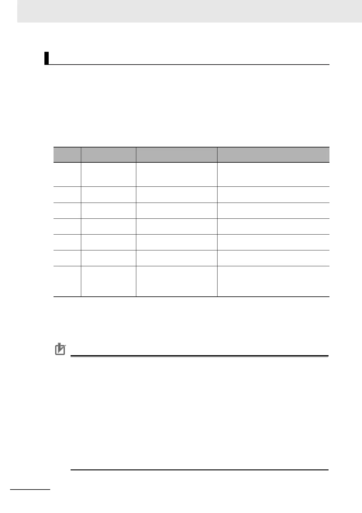
Setting Inverter I/O Functions
Parameter
No.
Function name Data Description
AA101
Main speed input
source selection,
1st-motor
14: Program function Set parameters to 14 (program function)
when frequency is set to variable
SET-Freq.
*a
*a. Set main speed input source selection [AA101] and Run-command input source selection [AA111] to other
than the values mentioned earlier. That enables LCD operator and analog signal to give speed/operation com-
mand.
CA-01 to
CA-11
Input terminal 1 to 9,
A and B
86 to 96: Ml1 to MI11
PRG: EzSQ Function PRG Terminal
*b
*b. Only when EzSQ function enable is set to PRG terminal start ([UE-02=01), assign 099 [PRG] to the input ter-
minal.
CC-01 to
CC-07
Output terminal 11 to
15 function
69 to 75: MO1 to MO7 MO1 to MO7 General-purpose output 1 to 7
Cd-03
FM monitor output
selection
Cd-03 YA(0): General-purpose analog output
Cd-04
Ao1 monitor output
selection
Cd-04 YA(1): General-purpose analog output
Cd-05
Ao2 monitor output
selection
Cd-05 YA(2): General-purpose analog output
AC-01
Acceleration/
Deceleration Time
input selection
04: DriveProgramming When acceleration/deceleration time is set
to variables ACCEL and DECEL, set Main
speed input source selection, 1st-motor
[AA101] to 14 (Program function).

 Loading...


