B7A/B7AS
B7A/B7AS
21
Operation
Power Supply
There
are normal-speed and high-speed 16-point models, which are dif
ferent in recommended transmission cable and transmission
distance.
If
only a single power supply is connected to either the input model or output model, the current on the power line will be limited.
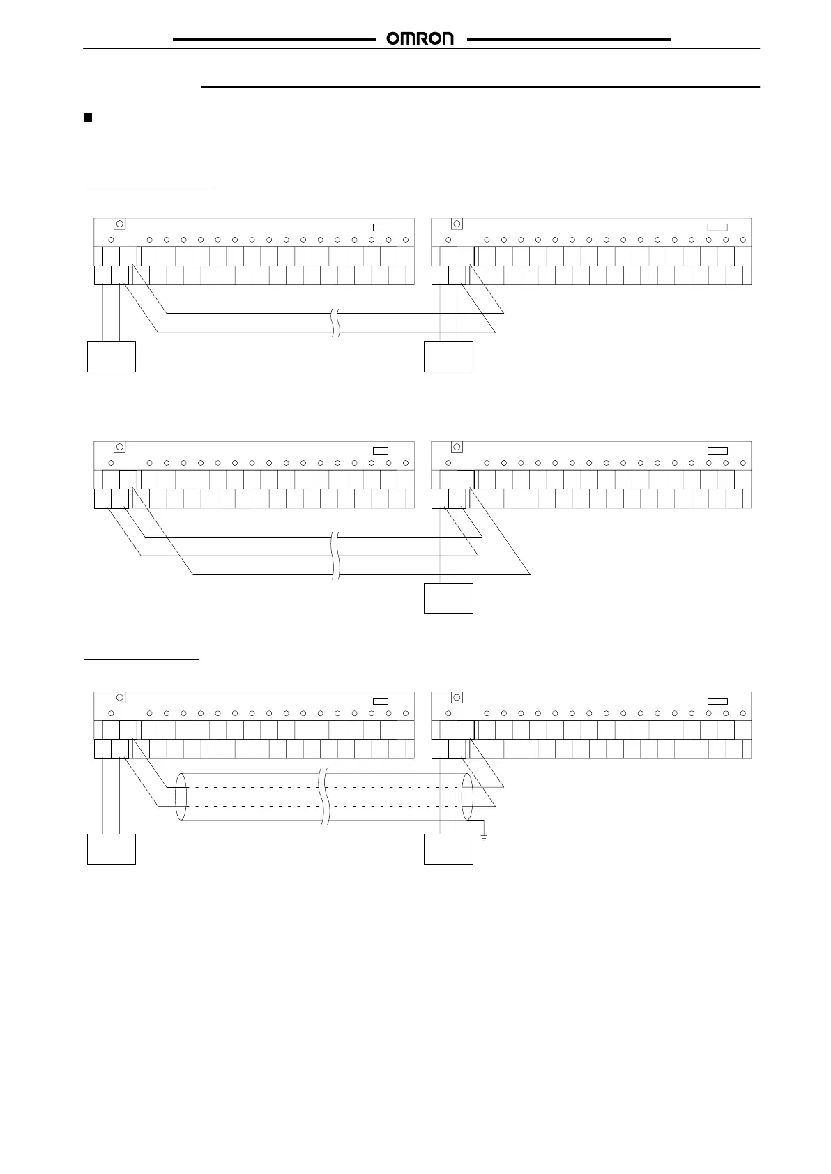
Screw Terminal Models
I/O
Delay: Normal Speed
Connection of Independent Power Supplies
IN
SIG
SIG
–
(–)
+
(+)
SIG
SIG
–
(–)
+
(+)
OUT
ERR
ERROR
Transmission distance
500 m max.
SIG
–
Note: A
VCTF cable with a thickness of 0.75 mm
2
min. must be used for signal transmission.
+–
DC power
supply
(12 to 24 V)
+–
DC power
supply
(12 to 24 V)
B7A/B7AS B7A/B7AS
Connection
of Single Power Supply to Input or Output T
erminal
SIG
SIG
–
(–)
+
(+)
SIG
SIG
–
(–)
+
(+)
ERR
ERROR
–
+
IN OUT
Note:
In this example, a VCTF transmission cable
with a thickness of 0.75 mm
2
is used,
through which a current of 1.8 A max. can
be transmitted.
+–
DC power
supply
(24 V)
SIG
Transmission distance
100 m max.
B7A/B7AS B7A/B7AS
I/O
Delay: High Speed
Connection of Independent Power Supplies
SIG
SIG
–
(–)
+
(+)
SIG
SIG
–
(–)
+
(+)
ERR
ERROR
SIG
–
IN OUT
Note:
In this example, a shielded cable with a thick
-
ness of 0.75 mm
2
min. is used for signal
transmission. It is recommended that the
shield be grounded.
The maximum transmission distance is 10 m if
a VCTF wire with a thickness of 0.75 mm
2
is
used instead of a shielded cable for the trans
-
mission path.
+–
DC power
supply
(12 to 24 V) (12 to 24 V)
Transmission distance
100 m max.
Shielded cable
+–
DC power
supply
GND
B7A/B7AS B7A/B7AS