B7AC
B7AC
79
Installation
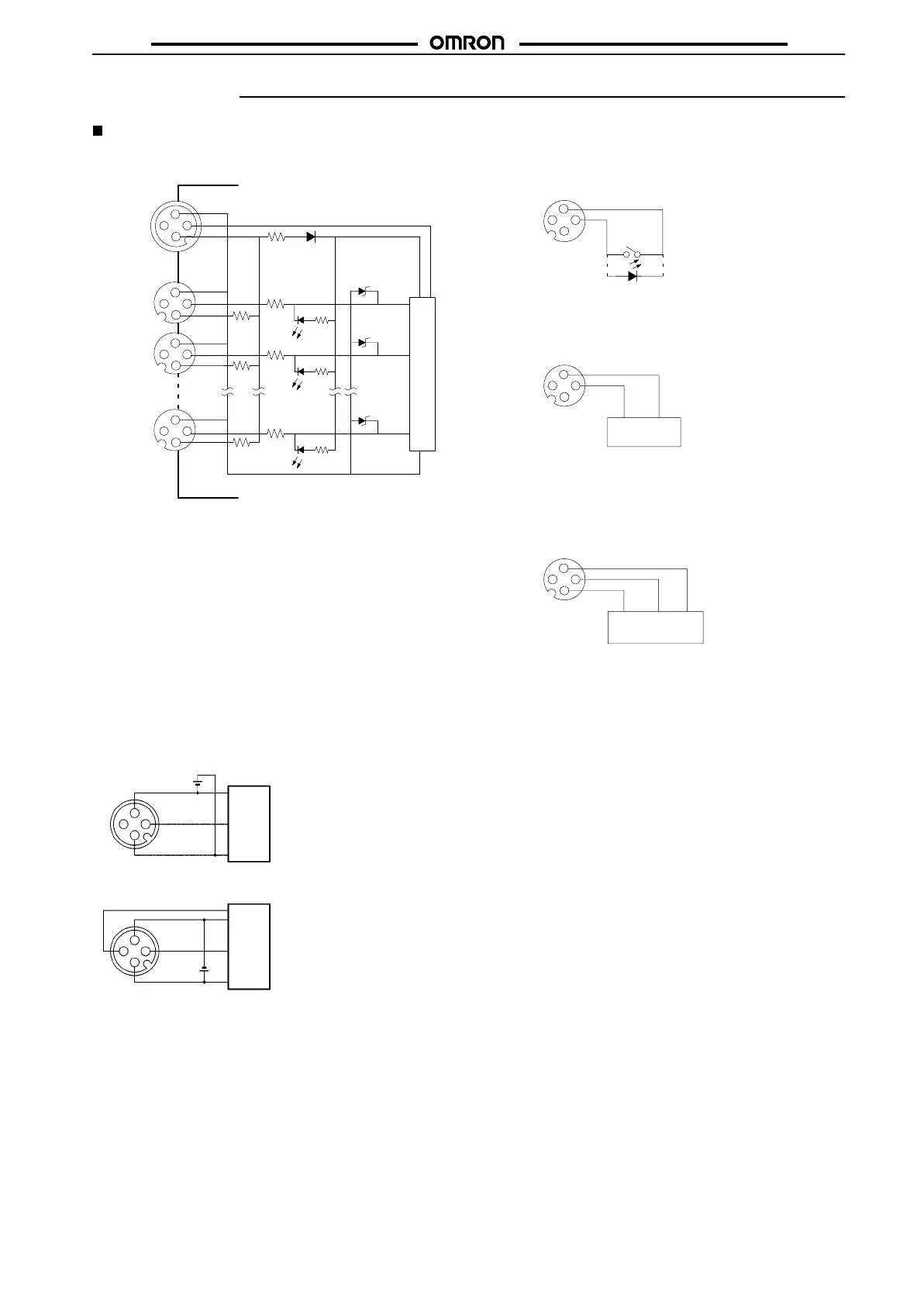
Internal Circuit
B7AC-T10A1/B7AC-T10A1-A
1
4
3
2
1
4
3
2
1
2
3
4
1
4
3
2
–
SIG
+
P
0
1
9
Intemal circuit
Connector
number
Connector No. 0 to 9 (Input)
With Contact Switch
W
ith T
wo-wire DC Sensor
With Three-wire NPN Sensor
Note: The permissible current
leakage
is 1.5 mA max.
Note: The contact arrangement of
the two-wire DC sensor does
not
conform to NECA 4202.
Note: The contact arrangement of the three-
wire
NPN
sensor corresponds to the nor
-
mally open output contact of the three-
wire DC sensor of NECA 4202.
Output
1
4
3
2
+–
1
4
3
2
Output –
1
4
3
2
Output –
Brown
(white)
Blue
(black)
Brown
(red)
Black
(white)
Blue
(black)
Connector No. P (Transmission)
Connection to B7A Output Unit
Power
supply
B7A Output Unit
Note: No connection is required to the I/O delay
selection
terminal (terminal 4).
Connection to DRT1-B7AC
Power
supply
DRT1-B7AC
Note: The
I/O delay time
can be selected by connecting
to the I/O delay selection terminal (terminal 4).
Selection
is made using the DR
T1-B7AC’s
selec
-
tion switch.
–
+
SIG
SPEED
–
SIG
+
4
3
2
1
4
3
2
1