B7AC
B7AC
80
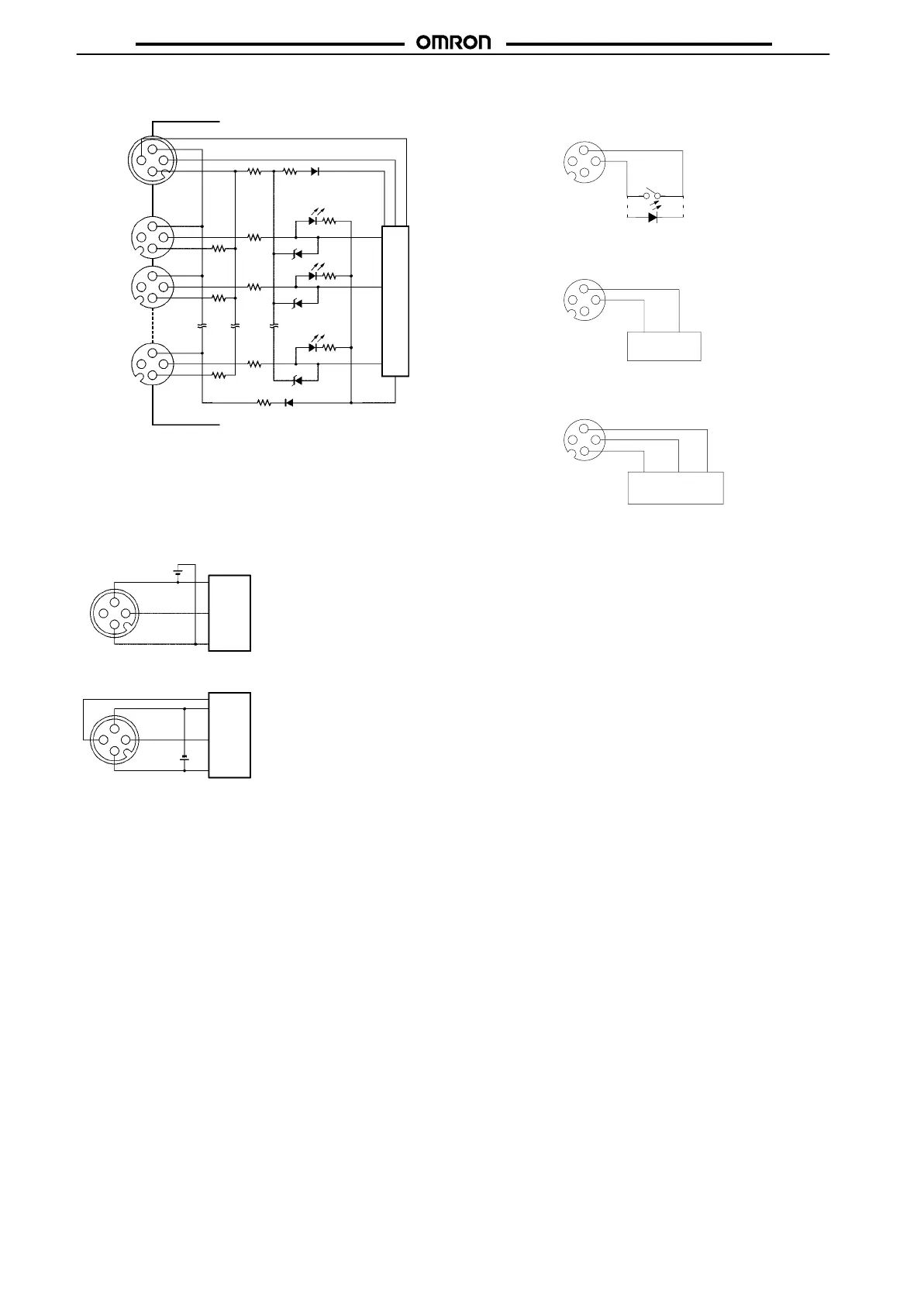
B7AC-T10A1-B
Intemal circuit
Connector
number
I/O delay time selection
4
3
2
1
4
3
1
2
4
3
1
2
4
3
1
2
9
1
0
P
36 V
36 V
36 V
–
SIG
+
Note: Terminal
2 of connector numbers 0 to 9 is not used.
Connector No. 0 to 9 (Input)
With Contact Switch
W
ith T
wo-wire DC Sensor
With Three-wire PNP Sensor
Output
1
4
3
2
+–
1
4
3
2
Output –
1
4
3
2
Output –
Brown
(white)
Blue
(black)
Brown
(red)
Black
(white)
Blue
(black)
Connector No. P (Transmission)
Connection to B7A Output Unit
Power
supply
B7A Output Unit
Note: No connection is required to the I/O delay
selection
terminal (terminal 4).
Connection to DRT1-B7AC
Power
supply
DRT1-B7AC
Note: The
I/O delay time can be selected by connect
-
ing
to the
I/O delay selection terminal (terminal
4).
Selection
is made using the DR
T1-B7AC’s
selection switch.
4
3
2
1
–
SIG
+
4
3
2
1
–
SIG
+
SPEED