B7A/B7AS
B7A/B7AS
30
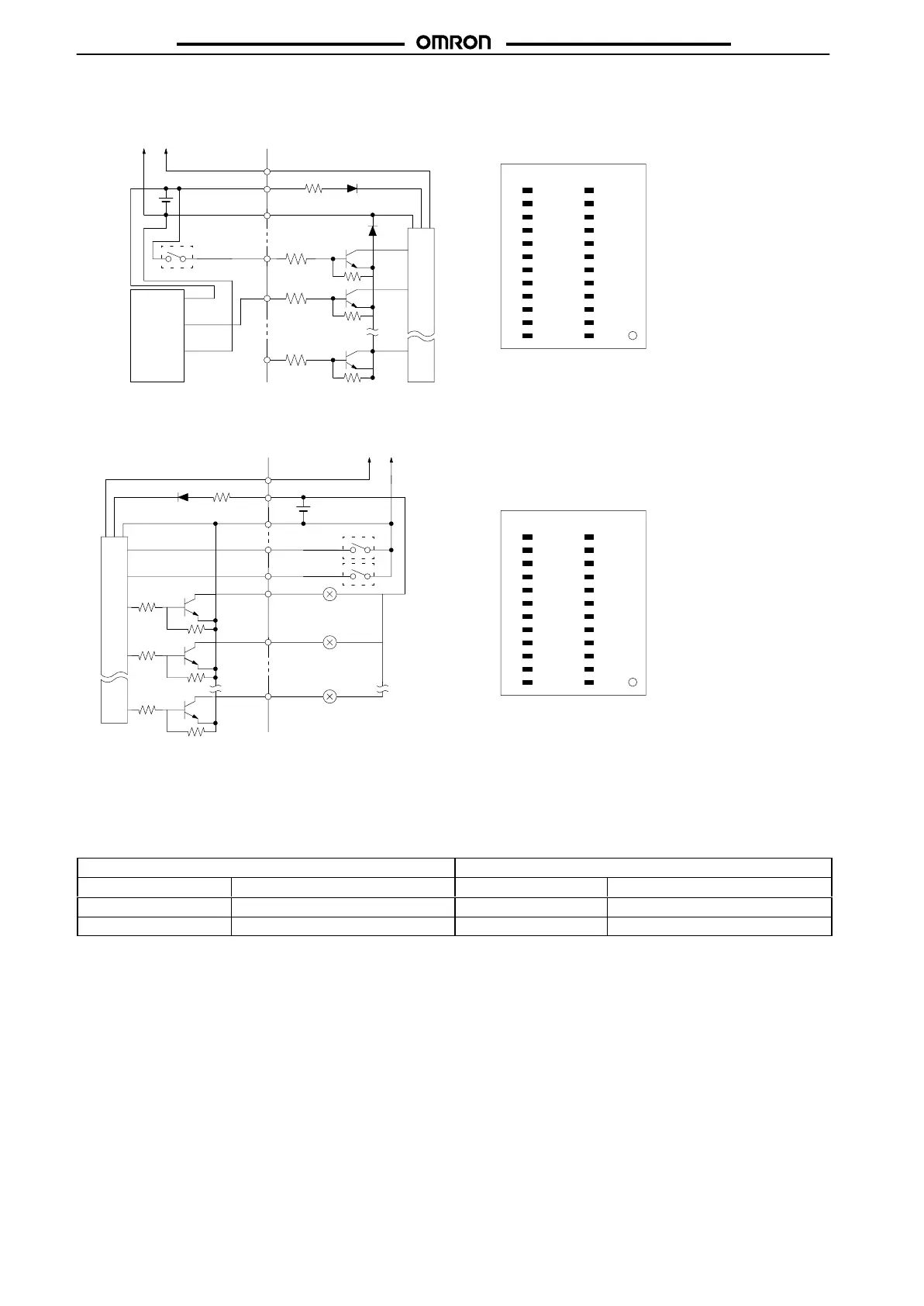
Modular Models
B7A-T6D2/-T6D7
(Input,
Active High)
B7A-R6A52/-R6A57
(Output, NPN Open Collector)
Black
(white)
Blue
(black)
Brown
(red)
Proximity
sensor
(with PNP
output)
–
+
SIG
Switch
Trans-
mission
line
Internal circuit
IN1013
IN1114
IN1215
IN1316
IN1417
IN1518
NC19
NC20
NC21
SIG22
NC23
+24
–12
NC11
IN0910
IN089
IN078
IN067
IN056
IN045
IN034
IN023
IN012
IN001
Top
V
iew
Note: 1. The wire colors have been changed in accordance
with
the revision of the Japanese Industrial Standards
for photoelectric sensors and proximity sensors. The
colors
in parentheses refer to the old colors.
2. Do
not short-circuit the SIG terminal with
a positive or
negative
power supply terminal, otherwise the
internal
elements
of the
B7A will be damaged and no transmis
-
sion
will be possible.
OUT1013
OUT1114
OUT1215
OUT1316
OUT1417
OUT1518
ERR19
N/P20
H/L21
SIG22
NC23
+24
–12
NC11
OUT0910
OUT089
OUT078
OUT067
OUT056
OUT045
OUT034
OUT023
OUT012
OUT001
T
op V
iew
N/P
+
SIG
Switch
(see
note 2)
H/L
ERR
–
Trans-
mission
line
Internal circuit
Note: 1. Do
not short-circuit any output terminal with the posi
-
tive terminal, otherwise the internal elements of the
B7A
will be damaged.
2. Logic output processing and error output processing
methods can be selected with the selectors. The se-
lectors
are not required when the B7A is used with its
output
fixed to the output logic.
INjj
INjj
INjj
OUTjj
OUTjj
Switch
(see
note 2)
N/P:
Negative/Positive
H/L: HOLD/LOAD OFF
T
erminal processing
Function T
erminal processing
Function
Open
Output logic active H
Open
Error output processing: HOLD
Connected to 0 V
Output logic active L
Connected to 0 V
Error output processing: LOAD OFF