B7A
B7A
41
Installation
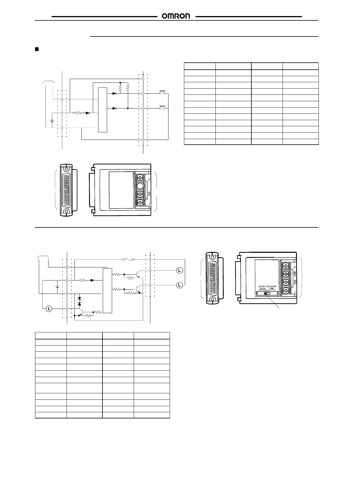
Internal Circuits and Terminal Arrangement
16-point Terminals
B7A-T6E3/-T6E8
(Input, Active Low)
–
SIG
12
to
24 VDC
Terminal
board
Internal circuit
IN00
IN15
to
+
+
_
Transmission
line
Terminal
board
Connector
Connector
Terminal
No.
Terminal T
erminal No.
Terminal
1 IN00 13 IN08
2 IN01 14 IN09
3 IN02 15 IN10
4 IN03 16 IN11
5 IN04 17 IN12
6 IN05 18 IN13
7 IN06 19 IN14
8 IN07 20 IN15
9 – 21 –
10 + 22 +
11 NC (open) 23 NC (open)
12 NC (open) 24 NC (open)
Note: Do
not short-circuit the SIG terminal with a positive or
nega
-
tive
power supply terminal, otherwise
the internal elements
of
the B7A will be
damaged and no transmission will be pos
-
sible.
B7A-R6A13/-R6A18/-R6A33/-R6A38
(Output, NPN Open Collector)
Internal circuit
12
to
24 VDC
ERR
Terminal
board
Connector
OUT00
OUT15/ERR
to
+
_
Transmission
line
SIG
Connector
Terminal
board
I/O output or error output
can be selected.
+ (9, 21)
(see note 2)
(see note 1)
Fuse
(see note 3)
(See note 1)
Terminal
No.
Terminal T
erminal No.
Terminal
1 OUT00 13 OUT08
2 OUT01 14 OUT09
3 OUT02 15 OUT10
4 OUT03 16 OUT11
5 OUT04 17 OUT12
6 OUT05 18 OUT13
7 OUT06 19 OUT14
8 OUT07 20 OUT15/ERR
(see
note 1)
9 + (see note 2) 21 + (see note 2)
10 NC (open) 22 NC (open)
11 NC (open) 23 NC (open)
12 NC (open) 24 NC (open)
Note: 1. It
is possible to select 16 I/O
points or 15 I/O points and 1
error
output point.
2. A
maximum of 0.4 A can be supplied from each
positive
terminal.
3. The
user cannot replace the fuse.
4. Do
not
short-circuit any output terminal with the positive
terminal, otherwise the internal elements of the B7A will
be
damaged.