B7A
B7A
43
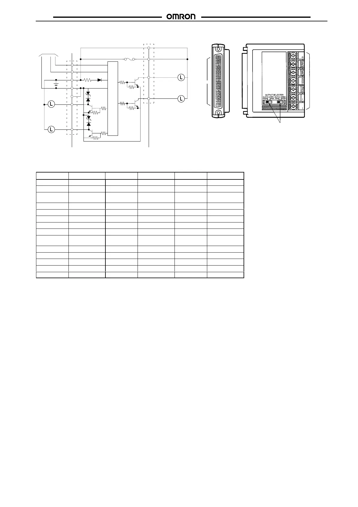
B7A-R3A13/-R3A33/-R3A18/-R3A38
(Output, NPN Open Collector)
ERR2
Transmission
line
SIG1
SIG2
+
_
12
to
24 VDC
Internal circuit
Connector
ERR1
Terminal
board
OUT00
OUT31/ERR
to
+ (18, 38)
• SIG1: OUT00
to OUT15
SIG2: OUT16 to OUT31
I/O
output or error
output can be selected.
Terminal
board
Connector
+ (9, 29)
(see note 2)
(see note 1)
Fuse
(see note 3)
(See note 1)
Terminal
No.
Terminal T
erminal No.
Terminal T
erminal No.
Terminal
1 OUT00 15 OUT13 29 + (see note 2)
2 OUT01 16 OUT14 30 OUT24
3 OUT02 17 OUT15/ERR
(see note 1)
31 OUT25
4 OUT03 18 + 32 OUT26
5 OUT04 19 NC (open) 33 OUT27
6 OUT05 20 NC (open) 34 OUT28
7 OUT06 21 OUT16 35 OUT29
8 OUT07 22 OUT17 36 OUT30
9 + (see note 2) 23 OUT18 37 OUT31/ERR
(see note 1)
10 OUT08 24 OUT19 38 +
11 OUT09 25 OUT20 39 NC (open)
12 OUT10 26 OUT21 40 NC (open)
13 OUT11 27 OUT22
14 OUT12 28 OUT23
Note: 1. It
is possible to select 32 output points or 30 output points and two error output points.
2.
A maximum of 0.4 A can be supplied from each positive terminal (9, 29).
3.
The user cannot replace the fuse.
4. Do
not short-circuit any output terminal with the positive terminal, otherwise the internal
elements
of the B7A will be damaged.