BN75R/BN150R/BN300R
1
2
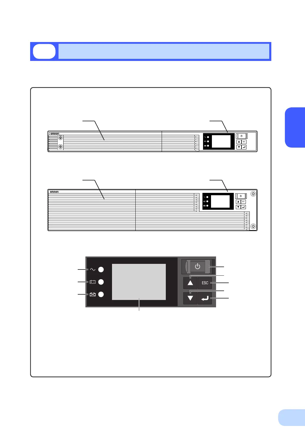
This section describes the name of each part of the UPS.
For information on the function of each part, refer to "2. Installation and connection" on page 5 and
"3. Operation" on page 24 that provides the details.
Front view
A.“Powersupplyoutput”LED
B.“Batterymode”LED
C.“Batteryreplacement”LED
D.LiquidCellDisplay
E.“Power”switch
F.“Up”switch
G.“Down”switch
H.“ESC”switch
I.“Enter”switch
1-3
Name of each part
< Enlarged view of the operation panel>
<BN75R>
<BN150R/BN300R>
BN75R
<Air vent>
<Air vent>
<Operation panel>
<Operation panel>
BN150R
A
E
H
I
F
G
B
C
D