EN-28
Parameter Table
Note: Factory settings are in bold.
Param.
Num.
Name Description
Initialize Data
A1-00
Language
selection for
Digital Opera-
tor display
(JVOP-160-OY
only)
0:English
1:Japanese
2:German
3:French
4:Italian
5:Spanish
6:Portuguese
A1-01
Parameter
access level
0:Monitoring only (Monitoring drive
mode and setting A1-01 and A1-04.)
1:Used to select user parameters (Only
parameters set in A2-01 to A2-32 can
be read and set.)
2:Advanced
(Parameters can be read and set in both,
quick programming mode (Q) and
advanced programming mode (A).)
A1-02
Control method
selection
0:V/f control
2: Open loop vector
3:Closed Loop Vector
6:Closed Loop Vector for PM motors
A1-03 Initialize
0: No initializing
1110:Initializes to user parameters
2220:.Initializes to the factory setting
Sequence/Reference Source
b1-01
Reference
source selection
0:Digital Operator
1:Control circuit terminal (analog input)
3:Option Card
b1-02
RUN com-
mand source
selection
0:Digital Operator
1:Control circuit terminal (digital
multi function inputs)
3:Option Card
Acceleration/Deceleration Settings
C1-
Accel./Decel.
time 1
Refer to page 1-22
C2-
S-curve charac-
teristic
Set the S-curve times at speed changes to
reduce the jerk. Refer to page 1-22
Slip Compensation
C3-01
Slip compensa-
tion gain
• Increase the value if slip compensation
value is too low
• Decrease the value if slip is overcom-
pensated
C3-02
Slip compensa-
tion delay time
• Reduce the value if the slip compensa-
tion responsiveness is low.
• When speed is not stable, increase the
setting.
Automatic Speed Regulator (ASR)
C5-01
ASR propor-
tional (P) gain 1
Set the proportional gain 1 and the inte-
gral time 1 of the speed control loop
(ASR) for the frequency C5-07.
C5-02
ASR integral (I)
time 1
C5-03
ASR propor-
tional (P) gain 2
Set the proportional gain 2 and the inte-
gral time 2 of the speed control loop
(ASR) for the minimum frequency.
The setting is active only for acceleration.
C5-04
ASR integral (I)
time 2
C5-06 ASR delay time Sets the ASR output delay time.
C5-07
ASR switching
frequency
Sets the frequency for switching between
Proportion Gain 1, 2,3 and Integral Time
1, 2, 3.
C5-09
ASR propor-
tional (P) gain 3
Set the proportional gain 3 and the inte-
gral time 3 of the speed control loop
(ASR) for the minimum frequency.
The settings is active for deceleration
only.
C5-10
ASR integral (I)
time 3
Carrier Frequency Setup
C6-02
Carrier fre-
quency selec-
tion 1
Selects the carrier frequency for Induc-
tion motor control modes.
C6-11
Carrier fre-
quency selec-
tion 2
Selects the carrier frequency for PM
motor control modes
Speed Settings
d1-01
to
d1-08
Multi speed ref.
1 to 8
Refer to page 19, Speed Selection
Sequence Using Digital Inputs
d1-09 Nominal speed
d1-10 Interm. speed 1
d1-11 Interm. speed 2
d1-12 Interm. speed 3
d1-13 Relevel. speed
d1-14 Inspect. speed
d1-17 Leveling Speed
d1-18
Speed priority
selection
0:Use Multi-Speed ref. (d1-01 to d1-08)
1:High Speed reference has priority.
2:Leveling speed reference has priority.
3:Use multi-speed reference
With no speed selected, the up/ down
signal is switched off
Refer to page 1-19
V/f Pattern Settings
E1-01
Input voltage
setting
This setting is used as a reference value
for protection functions.
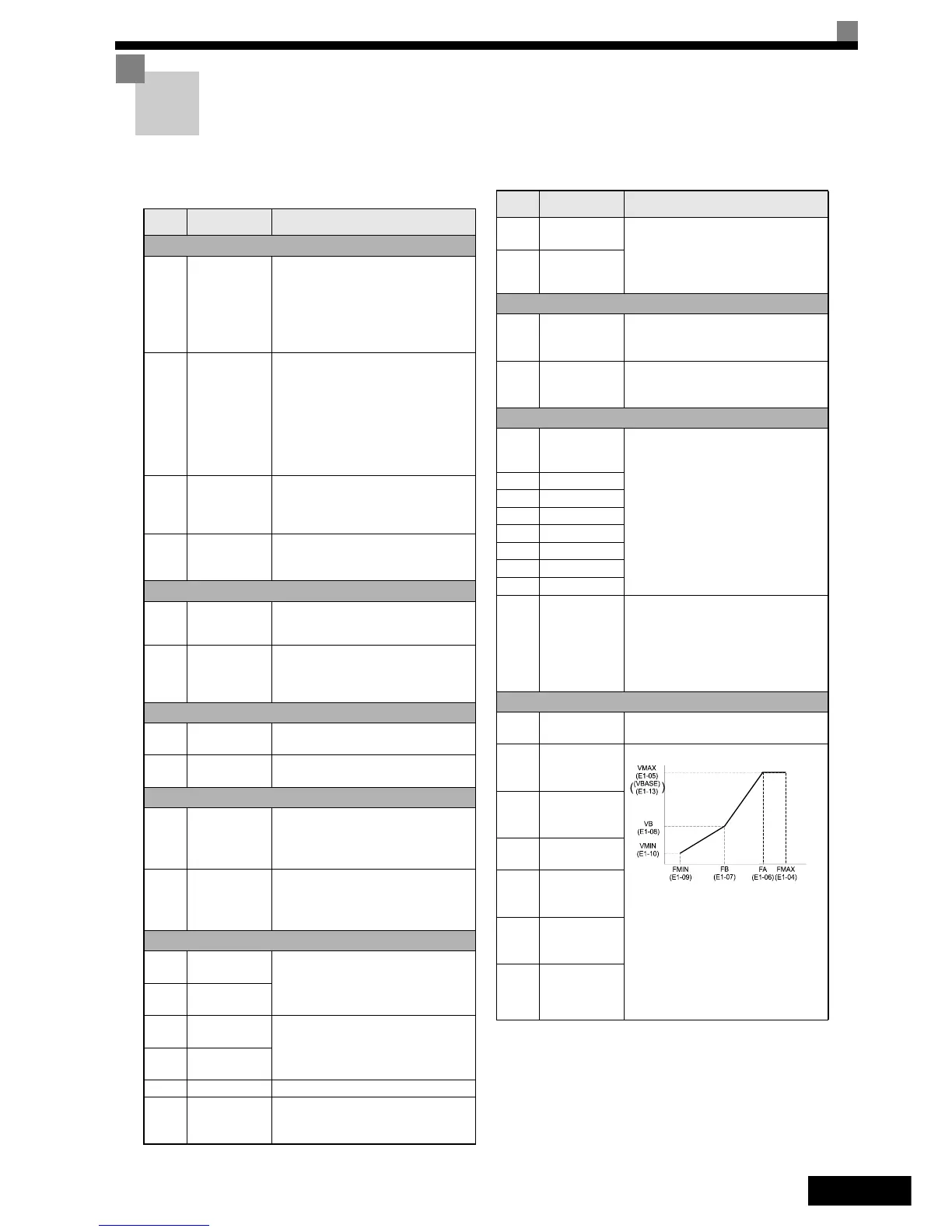
E1-04
Max. output
frequency
(FMAX)
To set V/f characteristics in a straight
line, set the same values for E1-07 and
E1-09. In this case, the setting for E1-08
will be disregarded.
Always ensure that the four frequencies
are set in the following manner:
E1-04 (FMAX) ≥ E1-06 (FA) > E1-07
(FB) ≥ E1-09 (FMIN)
E1-05
Max. output
voltage
(VMAX)
E1-06
Base frequency
(FA)
E1-08
Mid. output fre-
quency voltage
(VB)
E1-10
Min. output fre-
quency voltage
(VMIN)
E1-13
Base voltage
(VBASE)
Param.
Num.
Name Description
Output Voltage (V)
Frequency (Hz)
 Loading...