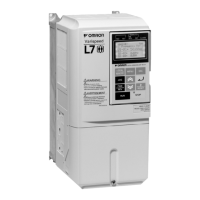
What does BUS Option Com Err (flashing) mean on Omron Inverter?
- KKirsten SanfordSep 12, 2025
If your Omron Inverter displays BUS Option Com Err (flashing), check the connections and all user-side software configurations.
What does BUS Option Com Err (flashing) mean on Omron Inverter?
If your Omron Inverter displays BUS Option Com Err (flashing), check the connections and all user-side software configurations.
What causes OV DC Bus Overvolt on Omron Inverter and how to fix it?
If you are experiencing an OV DC Bus Overvolt error with your Omron Inverter, consider these solutions: Increase the deceleration time or connect a braking option. Check the power supply and decrease the voltage to meet the inverter’s specifications. Also, inspect the braking chopper/resistor.
How to troubleshoot GF Ground Fault in Omron Inverter?
To troubleshoot a GF Ground Fault in your Omron Inverter, try these steps: Remove the motor and run the Inverter without the motor. Check the motor for a phase to ground short. Verify the output current with a clampmeter to verify the DCCT reading. Also, check the control sequence for wrong motor contactor signals.
What does CPF02 - CPF 04 mean on Omron CIMR-L7Z Inverter?
If your Omron Inverter displays CPF02 - CPF 04, perform an initialization to factory defaults. Cycle the Inverter power supply. Replace the Inverter.
What to do if Omron Inverter displays End - 1 V/f Over Setting?
If your Omron Inverter displays End - 1 V/f Over Setting, check and correct the motor settings. If the motor and the machine are connected, disconnect the motor from the machine.
What does SE1 Sequence Error 1 mean on Omron CIMR-L7Z Inverter?
If your Omron Inverter displays SE1 Sequence Error 1, check the output contactor.
What does OS Motor Over speed Det mean on Omron CIMR-L7Z Inverter?
If your Omron Inverter displays OS Motor Over speed Det, adjust the ASR settings in the C5 parameter group. Check the reference circuit and reference gain. Also, check the settings in F1-08 and F1-09.
What causes PGO PG Open (PG Disconnec- tion) on Omron CIMR-L7Z Inverter?
If you're experiencing PGO PG Open (PG Disconnec- tion) on your Omron Inverter, fix the broken/disconnected wiring. Supply power to the PG properly. Check the sequence and if the brake is opened when the inverter starts to increase the speed.
What does SE2 Sequence Error 2 mean on Omron CIMR-L7Z Inverter?
If your Omron Inverter displays SE2 Sequence Error 2, check the output contactor.
How to resolve DEV Speed Deviation error on Omron CIMR-L7Z Inverter?
To resolve a DEV Speed Deviation error on your Omron Inverter, reduce the load. Lengthen the acceleration time and deceleration time. Check the mechanical system. Also, check the settings of F1-10 and F1-11 and verify the sequence and if the brake is opened when the inverter starts to increase the speed.
Control Method | Sensorless Vector Control (SLV), V/f Control |
---|---|
Overload Capacity | 150% for 60 seconds |
Communication | Modbus RTU |
Protection Features | Overcurrent, Overvoltage, Undervoltage, Overheat, Ground fault, Short circuit |
Cooling Method | Fan-cooled |
Operating Temperature | -10°C to +50°C |
Humidity | 5-95% (non-condensing) |
Altitude | Up to 1000m without derating |
Enclosure Rating | IP20 |
General safety, intended use, installation, transportation, and storage guidelines.
Measures for electromagnetic compatibility and proper cable laying for reduced interference.
Procedures for unpacking, checking the site, and optimal inverter orientation for cooling.
Guidelines for connecting inverters, EMC filters, main circuit, output, and ground connections.
Rules for separating control wiring from main circuits and proper grounding of shields.
Explanation of drive status indicators, data display, and mode display elements.
Description of each key and its function for inverter control and parameter setting.
Step-by-step guide for initial power-up, control mode selection, and parameter setup.
Essential checks and preparations required before energizing the inverter.
How to interpret normal operation messages and fault indicators on the display.
Guidance on selecting the appropriate motor control mode based on motor type and encoder.
Choosing the correct autotuning mode based on control mode and motor characteristics for optimal performance.
Details of rotating, non-rotating, and resistance tuning procedures for motor data acquisition.
Common errors and fault codes encountered during autotuning and their corrective actions.
Detailed flowchart for performing autotuning on induction motors under various control modes.
Detailed flowchart for autotuning permanent magnet motors, including encoder setup.
Specific procedure to tune encoder offset if it has been changed or misaligned for PM motors.
Configuration of elevator travel direction commands and selection of speed references.
Setting up multi-step speed selections and their priority using digital inputs.
Tuning acceleration, deceleration times, and S-curve (jerk) for smooth motor response.
Understanding the standard timing and operation of the brake sequence during inverter control.
Enabling and tuning feed forward compensation for improved transient response and stability.
Identifying and interpreting fault and alarm codes displayed by the inverter for diagnosis.
Correcting parameter setting errors that prevent the inverter from operating or cause specific issues.
Detailed list of faults specific to the autotuning process and their troubleshooting steps.