EN-29
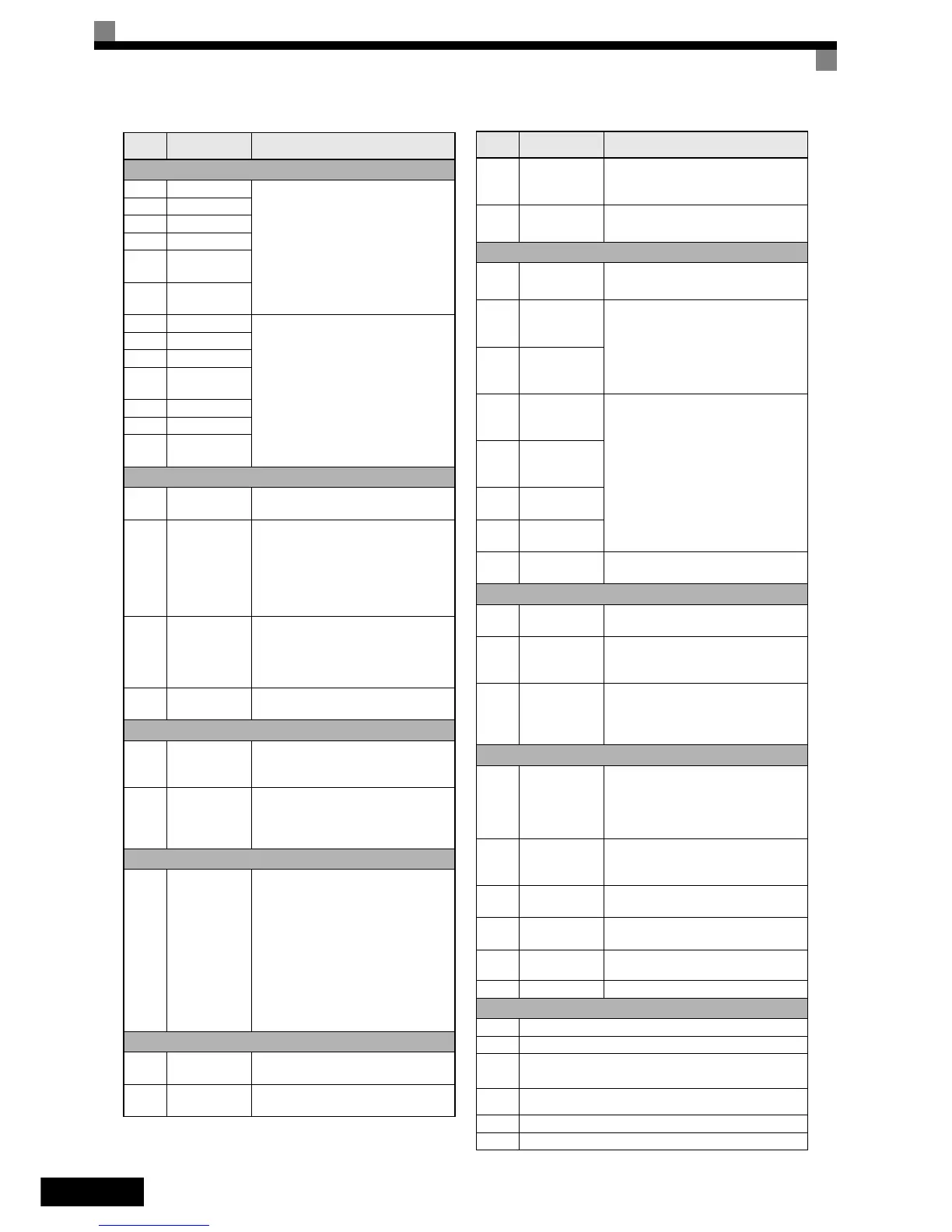
Motor Data Settings
E2-01 Rated current
Motor Data for induction motors
E2-02 Rated slip
E2-03 No-load current
E2-04 Pole number
E2-05
Line-to-line
resistance
E2-06
Leak induct-
ance
E5-02 Rated power
Motor Data for PM motors
E5-03 Rated current
E5-04 Pole number
E5-05
Line-to-line
resistance
E5-06 d-Inductance
E5-07 q- Inductance
E5-09
Motor voltage
constant
Encoder Feedback Settings
F1-01 PG constant
Sets the number of PG pulses per revolu-
tion
F1-05
PG rotation
direction
0:Phase A leads with forward run com-
mand. (Phase B leads with reverse
run command; Counter Clockwise
rotation)
1:Phase B leads with forward run com-
mand. (Phase A leads with reverse run
command; Clockwise rotation)
F1-21
Absolute
encoder resolu-
tion (Hiperface
or EnDat)
0:16384
1:32768
2:8192
(if EnDat is selected (n8-35=5), F1-21 is
fixed to 2)
F1-22
Magnet posi-
tion offset
Sets the Offset between the rotor magnet
and encoder zero position.
Digital I/O Settings
H1-01
to
H1-05
Terminal S3 to
S7 function
selection
Refer to the end of this list for a list of
selections
H2-01
to
H2-03
Terminal M1-
M2/M3-M4/
M5-M6 func-
tion selection
Refer to the end of this list for a list of
selections
Motor Protection
L1-01
Motor protec-
tion selection
0:Disabled
1:General-purpose motor protection
(fan cooled motor)
2:Inverter motor protection (externally
cooled motor)
3:Vector motor protection
When the Inverter power supply is
turned off, the thermal value is reset, so
even if this parameter is set to 1, pro-
tection may not be effective.
5:Permanent magnet constant torque
motor protection
Feed Forward Compensation
n5-01
Feed forward
control sel.
0:Disabled
1:Enabled
n5-02
Motor accelera-
tion time
Param.
Num.
Name Description
n5-03
Feed forward
proportional
gain
Speed reference response will increase as
the setting of n5-03 is increased.
n5-05
Motor accelera-
tion time tuning
0:Disabled
1:Enabled
Brake Sequence
S1-01
Zero Speed
level at stop
Sets the brake close command speed level
at stop.
S1-02
DC injection
braking current
at start
Sets as a percentage of the Inverter rated
current.
S1-03
DC injection
braking current
at stop
S1-04
DC inj. braking/
Zero speed time
at start
Refer to page 22, Brake Sequence.
S1-05
DC inj. braking/
Zero speed time
at stop
S1-06
Brake release
delay time
S1-07
Brake close
delay time
S1-20 Zero-servo gain
Zero servo position loop gain for closed
loop vector control.
Speed Reference Slip Compensation
S2-01
Motor rated
speed
Sets the motor rated speed.
S2-02
Slip compensa-
tion gain in
motoring mode
Sets the slip compensation gain in motor-
ing mode. Can be set for leveling accu-
racy improvement.
S2-03
Slip compensa-
tion gain in
regenerative
mode
Sets the slip compensation gain in regen-
erative mode.
It can be used to improve the
leveling accuracy.
Special Functions Setup
S3-01
Short-floor
function selec-
tion
Enables or disables the short floor opera-
tion function
0:disabled
1:enabled (Standard)
2:enabled (Advanced)
S3-04
Nominal/Lev-
eling speed
detection level
Nominal/Leveling speed detection level
when multispeed inputs are used. (d1-
18=0/3)
S3-08
Output phase
order
0:Output phase order is U-V-W
1:Output phase order is U-W-V
S3-13
Traction sheave
diameter
Sets the diameter of the traction sheave
for m/s display units.
S3-14 Roping Ratio
1:1:1
2:1:2
S3-15 Gear Ratio Sets the mechanical gear ratio.
Monitor Data
U1-01 Frequency reference in Hz/rpm
U1-02 Output frequency in Hz/rpm
U1-03 Output current in A
U1-05 Motor speed in Hz/rpm
U1-06 Output voltage in VAC
U1-07 DC bus voltage in VDC
Param.
Num.
Name Description
 Loading...


