202
Examples Section 4-2
6. PLC Setup Settings
These settings are the CPU Unit’s software configuration.
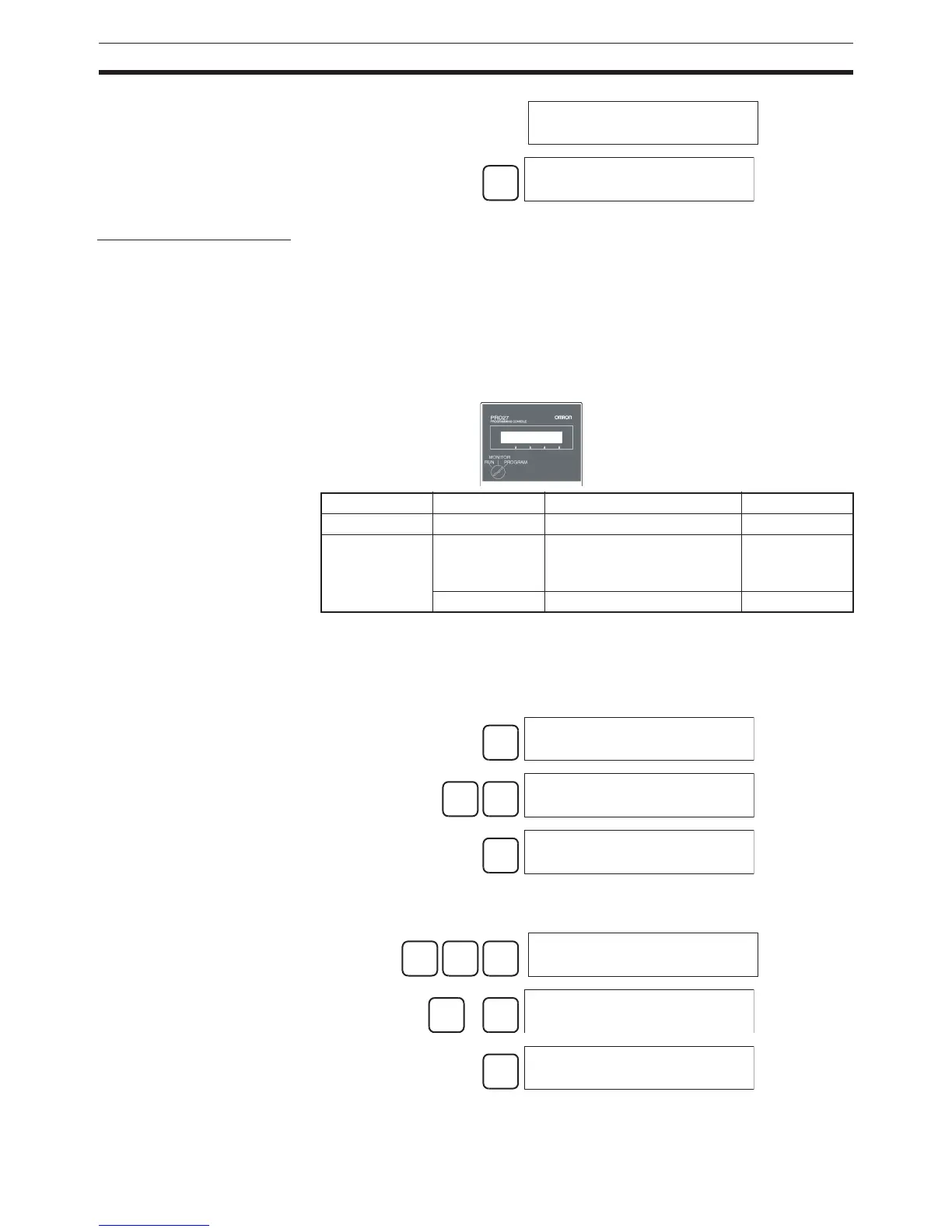
The PLC Setup settings are arranged by word addresses when a Program-
ming Console is used to make PLC Setup settings. This example shows a
Programming Console used to make the following settings:
• Set a Minimum Cycle Time in 1-ms units.
• Set a Watch Cycle Time (maximum cycle time) in 10-ms units.
Note When a host computer or PT is connected to the peripheral port or RS-232C
port, the port must be set for Host Link or NT Link communications in the PLC
Setup. When a standard serial device is connected, the port must be set for
no-protocol communications in the PLC Setup.
Specifying a word address in the PLC Setup.
(Example: 209)
or
Specify holding or clearing
CPU Bus Unit information.
000000 I/O TBL
WRIT OK
CLR
000000 CT00
Address Bits Setting Setting range
208 0 to 15 Minimum cycle time setting 0001 to 7D00
209 15 Enable for Watch Cycle Time
setting
0: Use default
1: Use setting in
bits 0 to 14.
0 to 14 Watch Cycle Time setting 0001 to 0FA0
Setting with a Programming Console
CLR
000000 CT00
FUN
VRFY
PC SETUP
0:MODE1:PC SETUP
1
PC SETUP
+000 0000
2
0
9
PC SETUP
+209
↓
↑
PC SETUP
+209 0000
CHG
PC SETUP?
+209 0000 0000
 Loading...


