203
Examples Section 4-2
Example: Input 8064.
7. DM Area Settings
The following table shows the parts of the DM Area are allocated to Special I/
O Units and CPU Bus Units for initial settings. The actual settings depend on
the model of Unit being used.
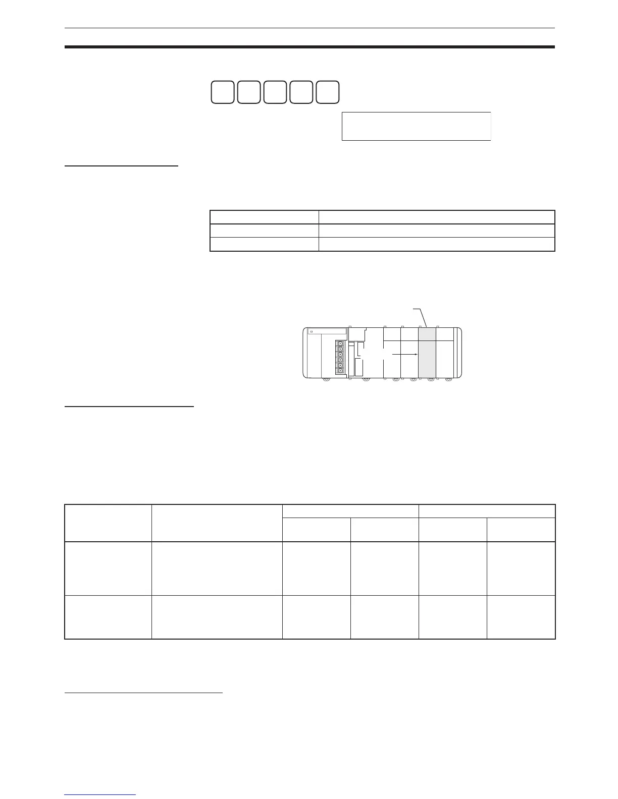
After writing the initial settings to the DM Area, be sure to restart the Units by
turning the PLC OFF and then ON again or toggling the Restart Bits for the
affected Units.
8. Writing the Program
Write the program with a Programming Device (CX-Programmer or Program-
ming Console).
The CJ-series PLC’s program can be divided into independently executable
tasks. A single cyclic task can be written for program execution like earlier
PLCs or several cyclic tasks can be written for a more flexible and efficient
program. The following table shows the differences when programming with
CX-Programmer or a Programming Console.
Note When writing the program with a Programming Console, specify whether
there are interrupt tasks during the memory clear operation.
9. Transferring the Program
When the program has been created in the CX-Programmer, it must be trans-
ferred to the PLC’s CPU Unit.
8
0
6
4
WRITE
+209 8064
PC SETUP
Unit Allocated words
Special I/O Units D20000 to D29599 (100 words × 96 Units)
CPU Bus Units D30000 to D31599 (100 words × 16 Units)
Special I/O Unit or
CPU Bus Unit
Restart
Programming
Device
Relationship between Tasks
and Program
Writing a new program Editing an existing program
Cyclic tasks Interrupt
tasks
Cyclic tasks Interrupt
tasks
Programming Con-
sole
Task = program
(Cyclic task 0 is the main pro-
gram)
Only one can
be written.
(Cyclic task 0)
Several can be
written.
(Interrupt tasks
1 to 3, 100 to
131)
All can be
edited.
All can be
edited.
CX-Programmer Specify the type of task and
task number for each program.
All can be writ-
ten.
(Cyclic tasks 0
to 31)
All can be writ-
ten.
(Interrupt tasks
0 to 255)
All can be
edited.
All can be
edited.
 Loading...


