204
Examples Section 4-2
10. Testing Operation
Before performing a Trial Operation in MONITOR mode, check the I/O wiring.
10-a) I/O Wiring Checks
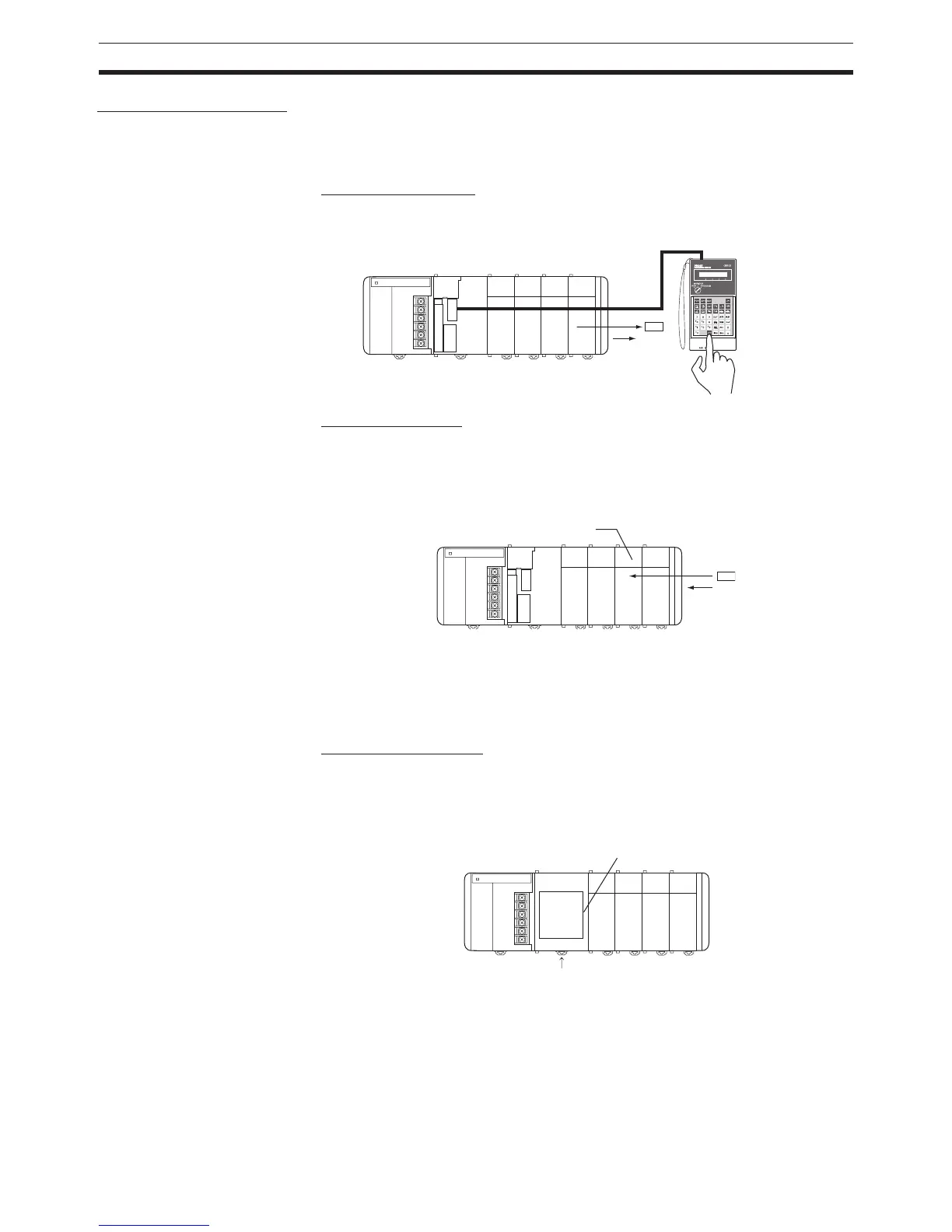
Check Output Wiring
With the PLC in PROGRAM mode, force-set and force-reset output bits and
verify that the corresponding outputs operate properly.
Check Input Wiring
Activate input devices such as sensors and switches and verify that the corre-
sponding indicators on the Input Units light. Also, use the Bit/Word Monitor
operation in the Programming Device to verify the operation of the corre-
sponding input bits.
10-b) Auxiliary Area Settings
Make any required Auxiliary Area settings, such as the ones shown below.
These settings can be made from a Programming Device (including a Pro-
gramming Console or the CX-Programmer) or instructions in the program.
IOM Hold Bit (A50012)
Turning ON the IOM Hold Bit protects the contents of I/O memory (the CIO
Area, Work Area, Timer Completion Flags and PVs, Index Registers, and
Data Registers) that would otherwise be cleared when the operating mode is
switched from PROGRAM mode to RUN/MONITOR mode or vice-versa.
Force-rese
Input Unit
Retained
Operating mode changed
I/O
memory
 Loading...


