2 Nomenclature and Installation
2-4
CJ-series PROFIBUS Slave Unit Operation Manual for NJ-series CPU Unit (W510)
The fieldbus connector is a 9-pin female sub-D connector, as recommended in the PROFIBUS stan-
dard EN50170 Vol.2.
Data Signal
The PROFIBUS User Group recommends the following color coding for the data signal lines:
A-line = Green B-line = Red
These data signal lines must be connected to the corresponding signal terminals or pins at the mas-
ter unit and other stations (i.e. A to A, B to B). For detailed PROFIBUS-DP cable requirements (see
2-3 Network Installation).
RTS
The signal RTS (TTL signal relative to DGND) is meant for the direction control of repeaters in case
repeaters without self control capability are used
VP, DGND
The signals VP and DGND are meant to power an externally
mounted bus terminator.
The powering of the 220 termination resistor ensures a
defined idle state potential on the data lines. To ensure proper
functioning up to the highest baud rate, each bus segment has
to be terminated at both ends of the cable.
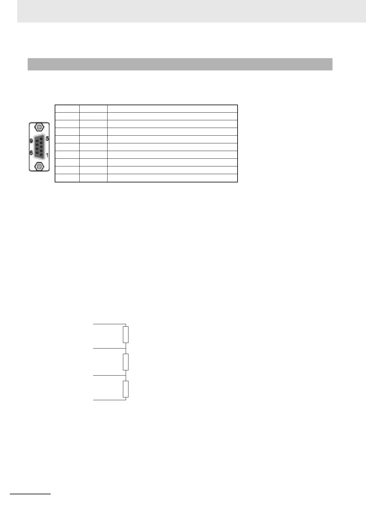
2-1-4 PROFIBUS Connector
Pin No. Signal Description
1 Shield Shield / functional ground
2- -
3 B-line Data signal
4 RTS Direction control signal for repeaters (TTL)
5 DGND Data ground
6 VP Supply voltage for terminator resistance (+5 VDC)
7- -
8 A-line Data signal
9- -
B-line
A-line
DGND
390
220
390
VP