3-3
3 Data Exchange with the CPU Unit
CJ-series PROFIBUS Slave Unit Operation Manual for NJ-series CPU Unit (W510)
3-2 I/O Data Mapping
3
3-2 I/O Data Mapping
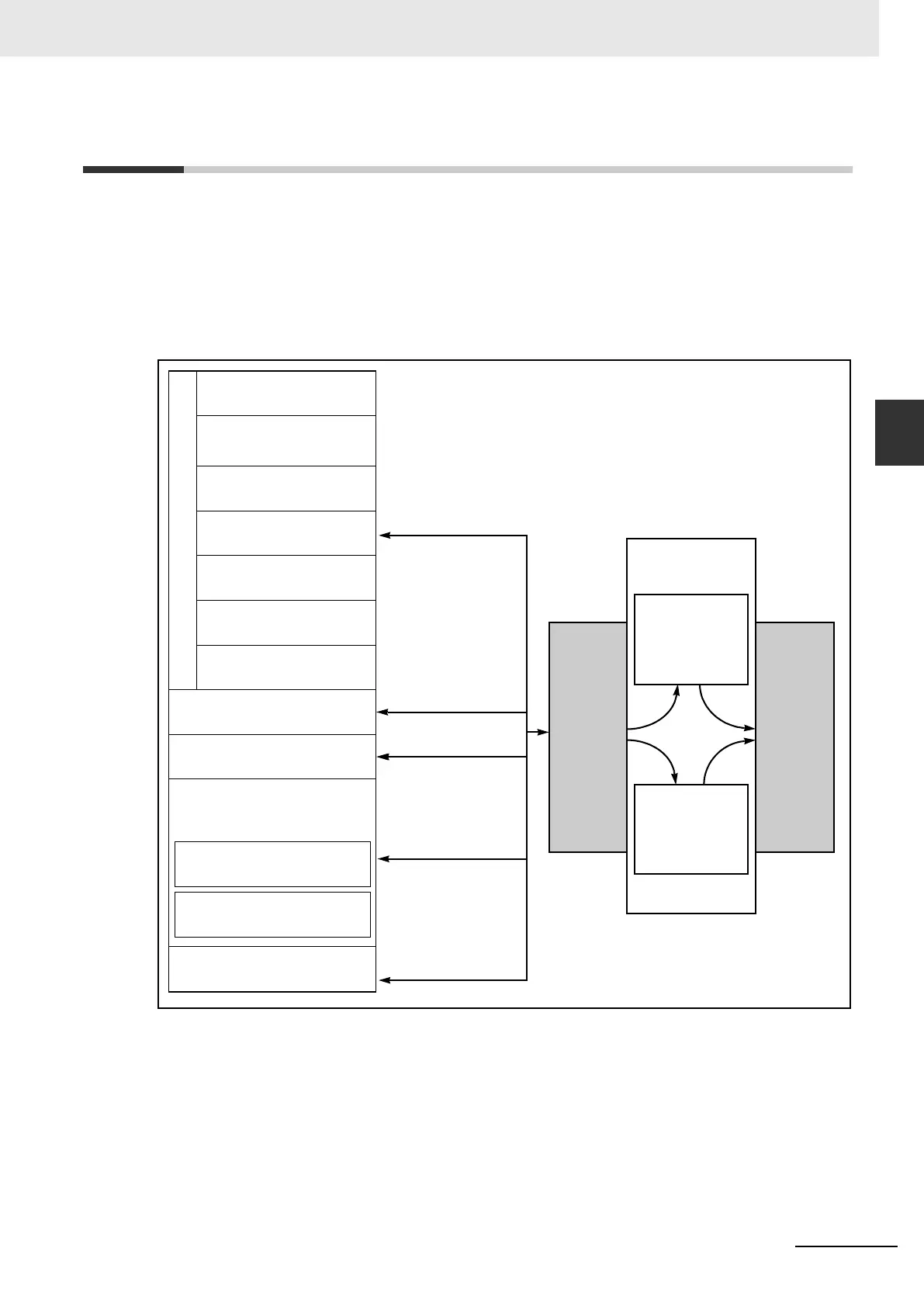
Data flow
The figure below shows the flow of remote I/O data in the CPU system. It is necessary to map the
PROFIBUS-DP I/O data to the areas of the CPU memory. The input and output areas can be
assigned independently. User-defined variables can be created and implemented in the User pro-
gram to access this data (see section 3-5 Data Exchange with the CPU Unit).
Note 1 Words that are not allocated can be used
2 Unused words can be used, but those areas may be used in future for expanding functions.
Slave input data is transferred via the I/O bus to the input buffer of the Unit. During each PROFIBUS-
DP cycle this data is transmitted to the master over PROFIBUS. Slave output data received from PRO-
FIBUS is first stored in the output buffer of the Unit. During an I/O refresh, this data is transferred to the
memory of the host CPU via the I/O Bus.
Host CPU
I/O BUS
CJ1W-PRT21
I/O Area
Data Link Area
CPU Bus unit area
Special I/O Unit Area
DeviceNet Area
Internal I/O Areas
(Not allocated words
1
)
(Not allocated words
1
)
(Not allocated words
1
)
(Not allocated words
1
)
(Not allocated words
1
)
CIO Area
I/O Area
(Not used
2
)
Work Area
Holding Area
Data Memory Area
Purposed for Special I/O
units (not allocated words
1
)
Purposed for CPU BUS
units (not allocated words
1
)
Extended Data Memory Area
Input + Output = max 180 words
(360 bytes)
Input buffer
(200 bytes)
Max. 100 words
PROFIBUS-DP
Input + Output = max 180 words
(360 bytes)
Output buffer
(200 bytes)
Max. 100 words