7 Wiring
7 - 6
NX-series EtherNet/IP Coupler Unit User’s Manual (W536)
7-2 Connecting the Power Supply and
Ground Wires
This section describes how to wire the power supplies and ground the EtherNet/IP Slave Terminal.
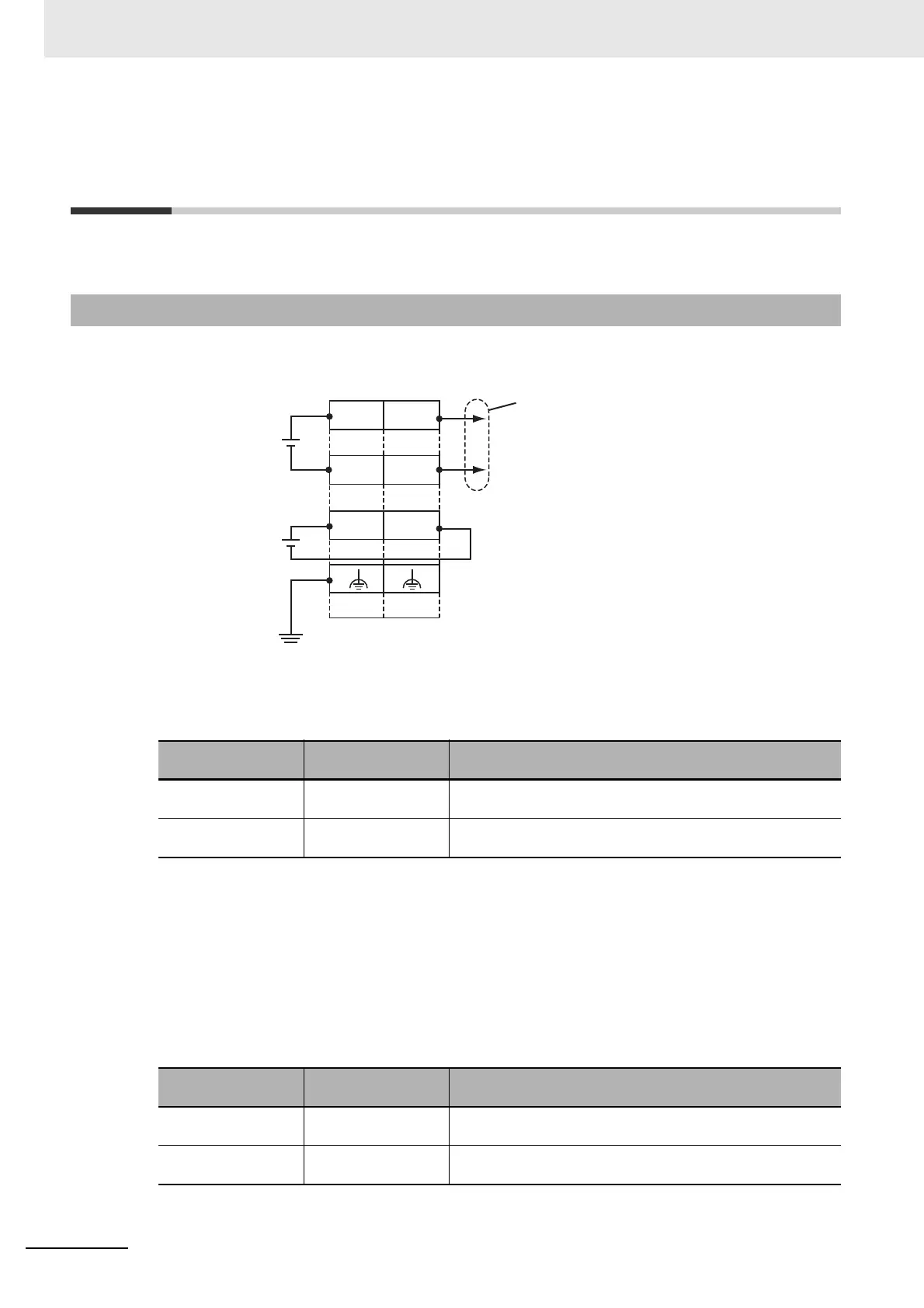
The wiring of the power supply and ground to the EtherNet/IP Coupler Unit is shown in the following fig-
ure.
Unit Power Supply Terminals
These terminals are connected to the Unit power supply. The details are given in the following table.
You can use the unwired terminals for through-wiring to an Additional NX Unit Power Supply Unit or
to the Unit power supply terminals on another EtherNet/IP Coupler Unit. Make the current supplied
from the unwired terminals meet the following conditions.
Current supplied from unwired terminals ≤ Current capacity of power supply terminals − Current
consumption of the EtherNet/IP Coupler Unit block
Refer to 5-4-1 Selecting the Unit Power Supply on page 5-16 for details on blocks.
I/O Power Supply Terminals
These terminals are connected to the I/O power supply. The details are given in the following table.
Provide a power supply voltage that is within the power supply voltage specifications of the NX Unit
I/O circuits and connected external devices.
7-2-1 Wiring the EtherNet/IP Coupler Unit
Terminal number
indication
Terminal name Description
A1 or B1 UV Connect the 24-VDC wire (positive side) from the Unit power
supply to either the A1 or B1 terminal.
A3 or B3 UG Connect the 0-VDC wire (negative side) from the Unit power
supply to either the A3 or B3 terminal.
Terminal number
indication
Terminal name Description
A5 IOV Connect the 5 to 24-VDC wire (positive side) from the I/O
power supply.
B5 IOG Connect the 0-VDC wire (negative side) from the I/O power
supply.
I/O power supply
(5 to 24 VDC)
Ground to
100 Ω or less
Through-wiring for unwired
terminals
IOV
UG
UV
IOG
UV
UG
A1
A8
B1
B8
Unit power
supply
(24 VDC)
 Loading...


