8 Using Expansion Units and Expansion I/O Units
8-18
CP1E CPU Unit Hardware User’s Manual(W479)
2
Wire to analog input devices.
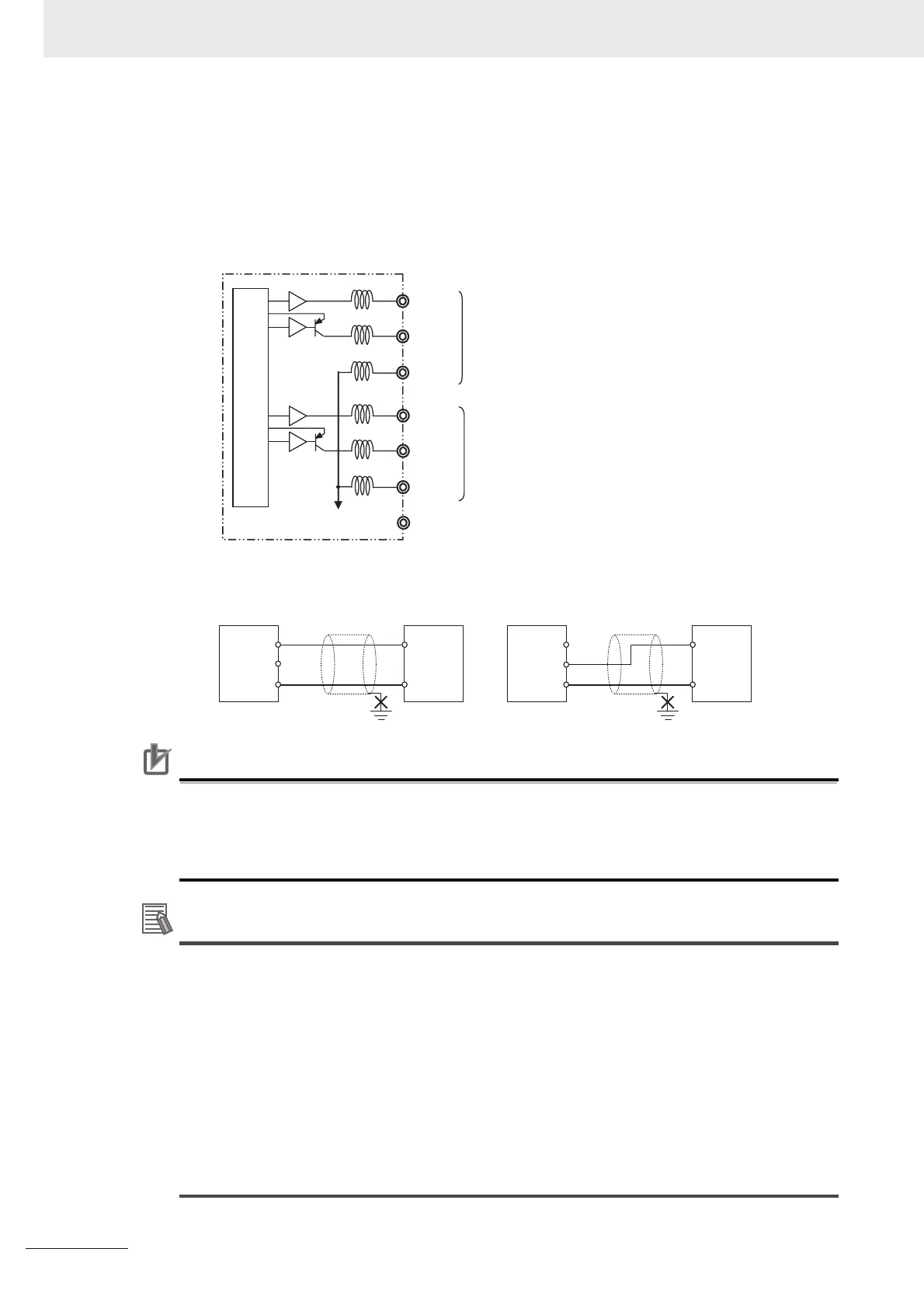
(1) Wiring internal circuits of the CPU Unit
The following diagram shows the internal circuit using CP1W-DA041 as an example, which
wires analog outputs 1 to 4. In the case of CP1W-DA021, analog outputs 1 to 2 can be
used.
(2) Wiring analog input devices to the Analog Output Unit
Precautions for Correct UsePrecautions for Correct Use
• Connect the shield to the FG terminal to prevent noise.
• Separate wiring from power lines (AC power supply lines, high-voltage lines, etc.)
• When there is noise in the power supply line, install a noise filter on the input section and the
power supply.
Additional Information
When external power is supplied (when setting the range code), or when there is a power inter-
ruption, a pulse-form analog output may be generated.
If this causes problems with operation, take countermeasures such as those suggested below.
(1) Countermeasure 1
• Turn ON the power supply for the CP1E CPU Unit first, confirm correct operation, and then
turn ON the power supply for the load.
• Turn OFF the power supply for the load before turning OFF the power supply for the CP1E
CPU Unit.
(2) Countermeasure 2
• Control the machine not only by analog output but also by other signals (additional start/stop
control signal for machine).
Analog output 1
Analog ground
NC
I OUT1
COM1 (−)
V OUT1
I OUT4
COM4 (−)
V OUT4
Analog output 4
Internal circuits
to
to
+
V OUT
COM
I OUT
−
+
V OUT
COM
I OUT
−
Analog
output
unit
Analog
device
with
voltage
input
Analog
output
unit
Analog
device
with
current
input
2-core shielded
twisted-pair cable
2-core shielded
twisted-pair cable
FG
FG