8-19
8 Using Expansion Units and Expansion I/O Units
CP1E CPU Unit Hardware User’s Manual(W479)
8-2 Analog Output Units
8
8-2-4 Flow of Operation
3
Create the ladder program.
(1) Allocating Output Words
Four output words (n+1 to n+4) are allocated to the Analog Output Unit starting from the
next word following the last allocated word on the CPU Unit or previous Expansion Unit or
Expansion I/O Unit. For CP1W-DA021, two output words (n+1, n+2) are allocated.
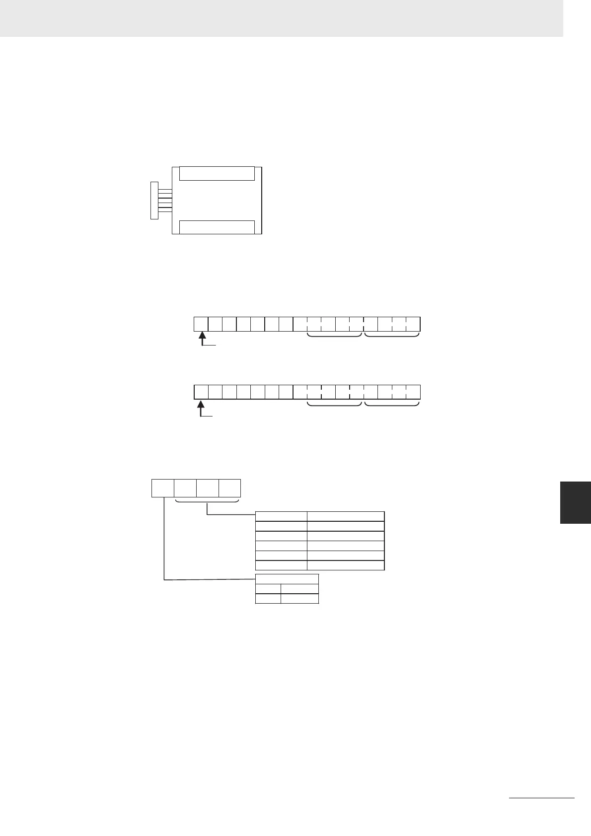
(2) Writing Set Data
Write the output use and the range code to words n+1 and n+2. For CP1W-DA021, only
word n+1 can be used. The D/A conversion will start when the set data is transferred from
the CPU Unit to the Analog Output Unit.
• Set Data
• The Analog Output Unit will not start converting analog I/O values until the range code
has been written. The output will be 0 V or 0 mA.
• After the range code has been set, 0 V or 0 mA will be output for the 0 to 10V, -10 to 10V,
or 0 to 20 mA ranges, and 1 V or 4 mA will be output for the 1 to 5V and 4 to 20 mA
ranges until a convertible value has been written to the output word.
• Once the range code has been set in the Analog Output Unit, it is not possible to change
the setting while power is being supplied to the CPU Unit. To change the I/O range, turn
the CPU Unit OFF then ON again.
Words n+1 to n+4
CP1W-DA041
Analog Output Unit
15
1 0 0 0 0 0 0
876543210
Wd n+1
15
1 0 0 0 0 0 0
876543210
0
0
Analog output 2 Analog output 1
Analog output 4
Analog output 3
Wd n+2
Even if analog outputs
are not used, bits 15 in
words n+1 and n+2
must be set to 1.
Even if analog outputs
are not used, bits 15 in
words n+1 and n+2
must be set to 1.
0
1
Range code
Analog output signal range
−10 to 10 V
0 to 10 V
1 to 5 V
0 to 20 mA
4 to 20 mA
000
001
010
011
100
Output use
No
Yes