8-33
8 Using Expansion Units and Expansion I/O Units
CP1E CPU Unit Hardware User’s Manual(W479)
8-3 Analog I/O Units
8
8-3-4 Flow of Operation
Additional Information
When external power is supplied (when setting the range code), or when there is a power inter-
ruption, a pulse-form analog output may be generated.
If this causes problems with operation, take countermeasures such as those suggested below.
(1) Countermeasure 1
• Turn ON the power supply for the CP1E CPU Unit first, confirm correct operation, and then
turn ON the power supply for the load.
• Turn OFF the power supply for the load before turning OFF the power supply for the CP1E
CPU Unit.
(2) Countermeasure 2
• Control the machine not only by analog output but also by other signals (additional start/stop
control signal for machine).
3
Create the ladder program.
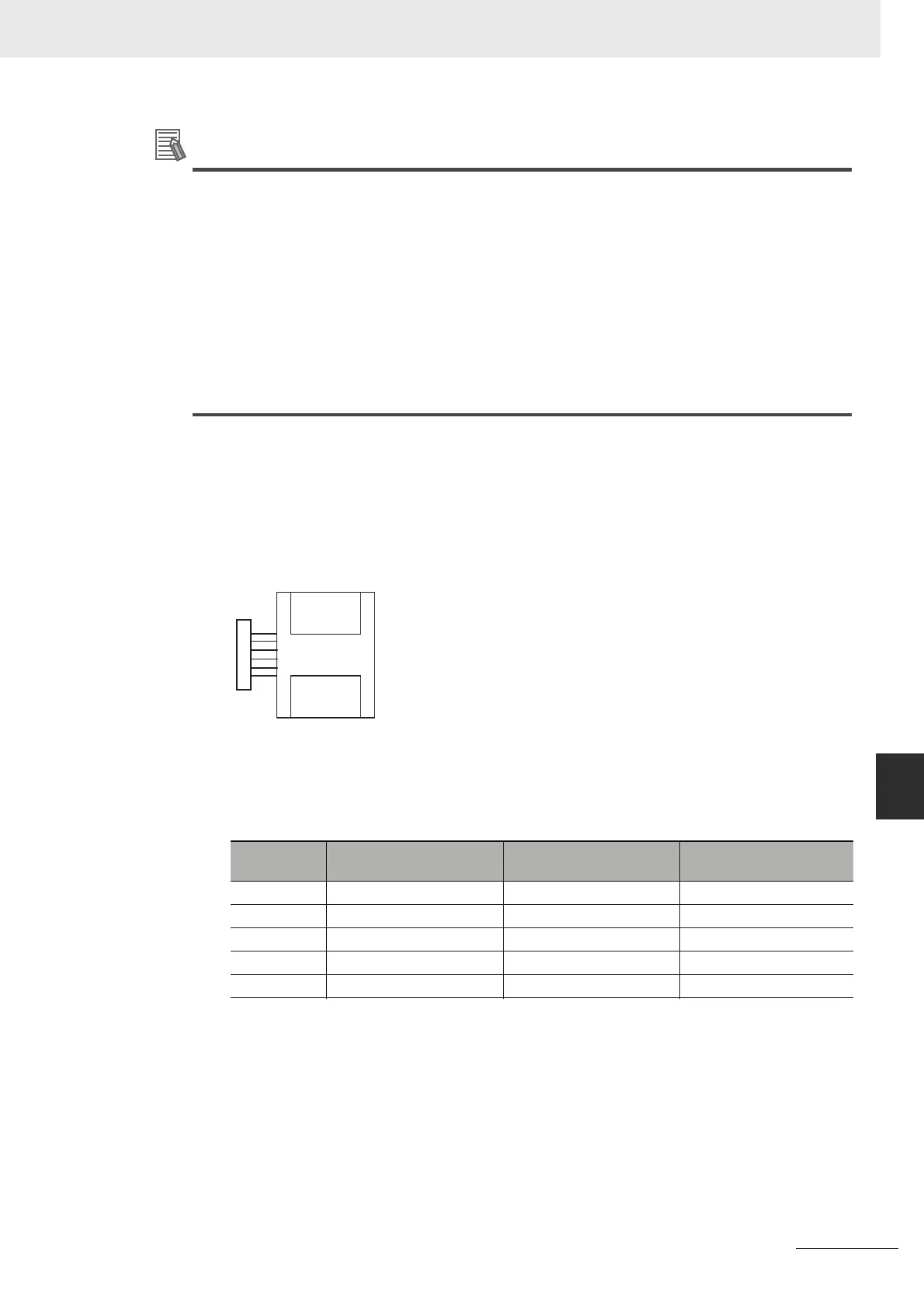
(1) Allocating I/O Words
Two input words and one output word are allocated to the Analog I/O Unit starting from the
next word following the last allocated word on the CPU Unit or previous Expansion Unit or
Expansion I/O Unit.
(2) Writing the Range Code
Write the range code to word n+1. A/D or D/A conversion begins when the range code is
transferred from the CPU Unit to the Analog I/O Unit. There are five range codes, 000 to
100, that combine the analog input 0 and 1 and analog output signal ranges, as shown
below.
Range code
Analog input 0 signal
range
Analog input 1 signal
range
Analog output signal
range
000 -10 to 10 V -10 to 10 V -10 to 10 V
001 0 to 10 V 0 to 10 V 0 to 10 V
010 1 to 5 V/4 to 20 mA 1 to 5 V/4 to 20 mA 1 to 5 V
011 0 to 5 V/0 to 20 mA 0 to 5 V/0 to 20 mA 0 to 20 mA
100 −−4 to 20 mA
Analog I/O Unit
Word m+1
Word m+2
32 inputs
16 outputs
Word n+1