3-17
3 Part Names and Functions
CP1E CPU Unit Hardware User’s Manual(W479)
3-1 CPU Units
3
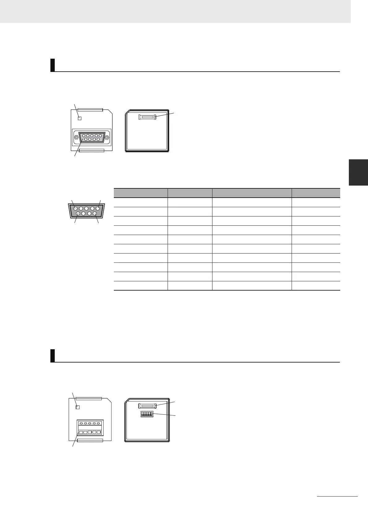
3-1-4 Optional Serial Communications Port for N/NA-type CPU Units
RS-232C Connector
Note The following devices can be connected to pin 6 (+5V) on the built-in RS-232C port on the CPU Unit or the
RS-232C Option Board (CP1W-CIF01) mounted to the CPU Unit. Do not connect pin 6 to any other device.
• RS-422A CJ1W-CIF11 Conversion Adapter
• RS-232C / RS-422A NT-AL001 Conversion Adapter
• NV3W-M20L Programmable Terminal
Built-in RS-232C Port and CP1W-CIF01 RS-232C Option Board
Pin Abbr. Signal Signal direction
1 FG Frame ground −
2 SD(TXD) Send data Outputs
3 RD(RXD) Receive data Inputs
4 RS(RTS) Request to send Outputs
5 CS(CTS) Clear to send Inputs
65V Power −
7 DR(DSR) Data set ready Inputs
8 ER(DTR) Data terminal ready Outputs
9 SG(0V) Signal ground −
Connector hood FG Frame ground −
CP1W-CIF11 or CP1W-CIF12 RS-422A/485 Option Board
COMM
Front Rear
Communications
status indicator
RS-232C connector
CPU Unit connector
5
6
1
9
Front Rear
Communications
status indicator
COMM
RDA- RDB+ SDA- SDB+ FG
RS-232C connector
CPU Unit connector
DIP switch for operation
settings