3 Part Names and Functions
3-18
CP1E CPU Unit Hardware User’s Manual(W479)
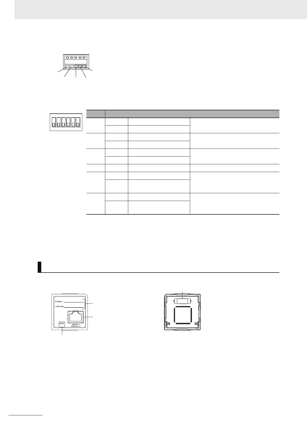
RS-422A/485 Terminal Block
DIP switch for operation settings
Pin Setting
1 ON ON (both ends) Terminating resistance selection
OFF OFF
2 ON 2-wire connections
2-wire or 4-wire selection
*1
OFF 4-wire connections
3 ON 2-wire connections
2-wire or 4-wire selection
*1
OFF 4-wire connections
4 −−Not used.
5 ON RS control enabled
RS control selection for RD
*2
OFF RS control disabled (Data
always received.)
6 ON RS control enabled
RS control selection for SD
*3
OFF RS control disabled (Data
always sent.)
*1 Set both pins 2 and 3 to either ON (2-wire) or OFF (4-wire).
*2 To disable the echo-back function, set pin 5 to ON (RS control enabled).
*3 When connecting to a device on the N side in a 1: N connection with the 4-wire method,
set pin 6 to ON (RS control enabled).
Also, when connecting by the 2-wire method, set pin 6 to ON (RS control enabled).
CP1W-CIF41 Ethernet Option Board
RDB+
RDA-
SDA-
SDB+
FG
Tighten screws on the terminal
block to 0.28 N
.
m.
1
2
3
4
5
6
O
N
Label
Attach the label here to show IP
address and subnet mask.
Front Rear
CPU Unit connector
Ethernet Connector
Used to connect the Ethernet
twisted-pair cable.
LED Indicators
Display the operating status of the Option Board.