3-19
3 Part Names and Functions
CP1E CPU Unit Hardware User’s Manual(W479)
3-1 CPU Units
3
3-1-4 Optional Serial Communications Port for N/NA-type CPU Units
LED Indicators
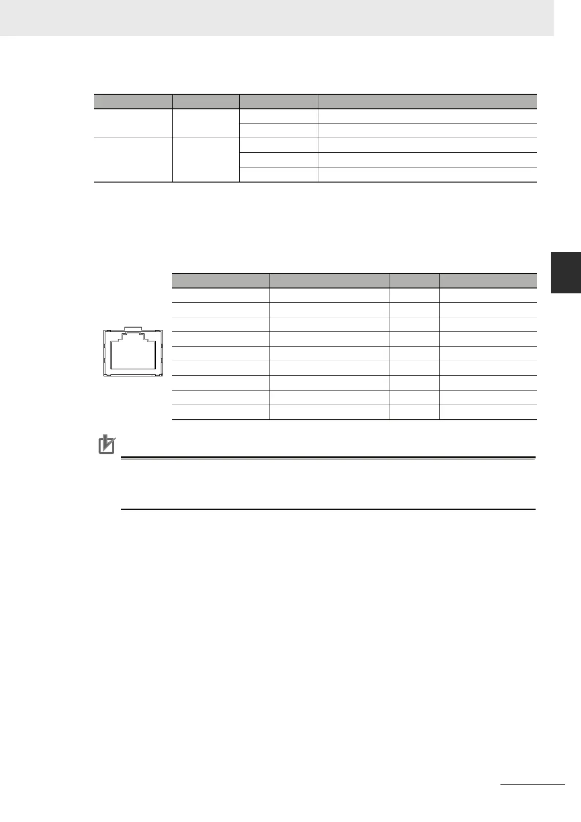
Ethernet Connectors
The following standards and specifications apply to the connectors for the Ethernet twisted-pair
cable.
Electrical specifications: Conforming to IEEE802.3 standards
Connector structure: RJ45 8-pin Modular Connector (conforming to ISO8877)
Precautions for Correct UsePrecautions for Correct Use
Connecting the Cable
• Turn OFF the PLC’s power supply before connection or disconnecting twisted-pair cable.
• Allow enough space for the bending radius of the twisted-pair cable.
Indicator Color Status Meaning
COMM Yellow Not lit Not sending or receiving data.
Flashing Sending or receiving data.
ERR Red Not lit Unit normal.
Lit An fatal error has occurred at the Unit.
Flashing An no-fatal error has occurred at the unit.
Connector Pin Signal Name Abbr. Signal Direction
1 Transmission data + TD+ Output
2 Transmission data - TD- Output
3 Reception data + RD+ Input
4 Not used --- ---
5 Not used --- ---
6 Reception data - RD- Input
7 Not used --- ---
8 Not used --- ---
Hood Frame ground FG ---