Home
Omron
Controller
CPM2A - 11-2005
Omron CPM2A - 11-2005 User Manual
4
of 1
of 1 rating
187 pages
Give review
Manual
Specs
To Next Page
To Next Page
To Previous Page
To Previous Page
Loading...
5-5
Section
T
roubleshooting Flowcharts
136
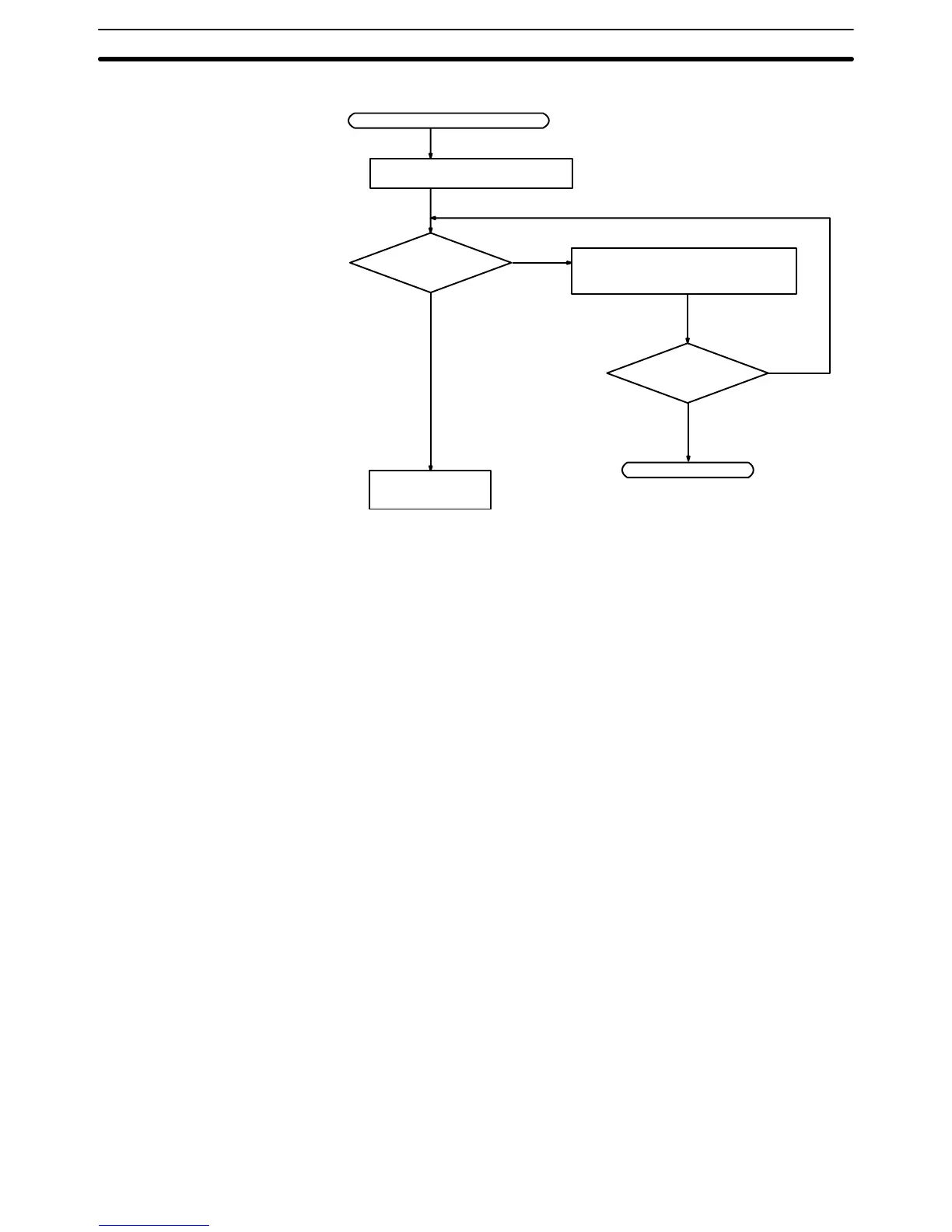
Non-fatal Error Check
Identify the error
, eliminate its
cause, and clear the error
.
ERR/ALM indicator flashing.
Is a non-fatal error
indicated?
Is the ERR/ALM
indicator flashing?
Replace the CPU
Unit.
End
Determine the cause of the error
with a Programming Device.
No
Ye
s
Flashing
Not lit
152
154
Table of Contents
Table of Contents
6
Precautions
13
Precautions
14
Intended Audience
14
General Precautions
14
Safety Precautions
14
Operating Environment Precautions
15
Application Precautions
16
EC Directives
18
CPM2A 24-VDC CPU Unit Conformance to NK Standards
21
Section 1 Introduction
22
Section 1
22
Introduction
22
CPM2A Features and Functions
23
CPM2A Features
23
Overview of CPM2A Functions
28
Basic System Configurations
30
Stand-Alone CPU Unit
30
CPU Unit, Expansion Units, and Expansion I/O Units
30
Structure and Operation
33
CPU Unit Structure
33
Operating Modes
34
Operating Mode at Startup
34
PC Operation at Startup
35
Cyclic Operation and Interrupts
36
Functions Listed by Usage
39
Comparison with the CPM1A
42
Preparation for Operation
47
Section 2 Unit Specifications and Components
49
Section 2
49
Specifications
50
General Specifications of CPU Units
50
Characteristics
51
I/O Specifications
53
Unit Components
57
CPU Unit Components
57
Expansion I/O Unit Components
60
Analog I/O Unit Components
61
Temperature Sensor Unit Components
62
Compobus/S I/O Link Unit Components
63
Devicenet I/O Link Unit Components
64
Unit Specifications and Components
49
Section 3 Installation and Wiring
66
Section 3
66
Installation and Wiring
66
Design Precautions
67
Selecting an Installation Site
67
Power Supply Wiring
67
Power Supply Voltage
67
Interlock and Limit Circuits
67
Installation Site Conditions
68
Panel/Cabinet Installation
68
Installing the CPM2A
69
CPM2A Orientation
69
CPM2A Installation
69
Connecting an Expansion Unit or Expansion I/O Unit
71
Wiring and Connections
72
General Precautions for Wiring
72
Removing the Terminal Block
73
Ground Wiring
74
Power Supply Wiring
75
Input Wiring
77
Output Wiring
85
Programming Device Connections
100
Host Link Connections
101
No-Protocol Communications
104
OMRON PT Connections
104
One-To-One PC Link Connections
105
Compobus/S I/O Link Connections
106
Section 4 Using a Programming Console
107
Section 4
107
Compatible Programming Consoles
108
Changing the Cpm2A's Mode with the Mode Switch
110
Connecting the Programming Console
111
Preparation for Operation
112
Entering the Password
112
Programming Console Operations
114
Overview
114
Clearing Memory
115
Clearing Memory Completely
116
Reading um Allocation Information
116
Reading/Clearing Error Messages
116
Buzzer Operation
117
Assigning Expansion Instruction Function Codes
118
Setting and Reading a Program Memory Address and Monitoring I/O Bit Status
118
Entering or Editing Programs
119
Instruction Search
122
Bit Operand Search
123
Inserting and Deleting Instructions
123
Checking the Program
125
Bit, Digit, Word Monitor
125
Differentiation Monitor
127
Binary Monitor
128
Three-Word Monitor
129
Signed Decimal Monitor
129
Unsigned Decimal Monitor
130
Three-Word Data Modification
130
Changing Timer, Counter SV
131
Hexadecimal, BCD Data Modification
132
Binary Data Modification
133
Signed Decimal Data Modification
133
Unsigned Decimal Data Modification
134
Force Set, Reset
135
Clear Force Set/Reset
136
Hex-ASCII Display Change
136
Displaying the Cycle Time
137
Reading and Setting the Clock
137
Programming Example
138
Preparatory Operations
138
Example Program
139
Programming Procedures
140
Checking the Program
143
Test Run in MONITOR Mode
143
Using a Programming Console
107
Section 5 Test Runs and Error Processing
144
Section 5
144
Initial System Checks and Test Run Procedure
145
Initial System Checks
145
Flash Memory Precautions
145
CPM2A Test Run Procedure
145
Self-Diagnostic Functions
146
Identifying Errors
146
User-Defined Errors
147
Non-Fatal Errors
147
Fatal Errors
148
Communications Errors
148
Programming Console Operation Errors
149
Programming Errors
149
Troubleshooting Flowcharts
150
Maintenance Inspections
158
Battery Replacement
159
Test Runs and Error Processing
144
Section 6 Expansion Memory Unit
161
Section 6
162
Expansion Memory Unit
162
Overview
162
Memory Areas
162
Precautions
162
Specifications and Nomenclature
163
Specifications
163
Nomenclature
163
Handling
164
Mounting/Removing EEPROM
164
PC Connections
165
Uploading Programs
166
SECTION 6 Expansion Memory Unit
166
Downloading Programs
168
4
Based on 1 rating
Ask a question
Give review
Questions and Answers:
Need help?
Do you have a question about the Omron CPM2A - 11-2005 and is the answer not in the manual?
Ask a question
Omron CPM2A - 11-2005 Specifications
General
Brand
Omron
Model
CPM2A - 11-2005
Category
Controller
Language
English
Related product manuals
Omron SYSMAC CPM2A
20 pages
Omron CPM2C
325 pages
Omron CPM1
144 pages
Omron CPM1A
201 pages
Omron SYSMAC CPM1
157 pages
Omron CP2E
47 pages
Omron CP1E-ED
262 pages
Omron CJ2M-CPU34
82 pages
Omron CJ2M-CPU33
82 pages
Omron CS1G-CPU42H
274 pages
Omron C200HE-CPU11
241 pages
Omron CJ1M-CPU series
347 pages