!
67
Note Refer to Section 3 Memory Areas in the Programming Manual (W353) for details
on the allocation of output bits in CPM2A PCs.
WARNING The PC outputs may remain ON or OFF due to deposition or burning of the
output relays or destruction of the output transistors. External safety measures
must be provided to ensure safety in the system. Not providing proper safety
measures may result in serious accidents.
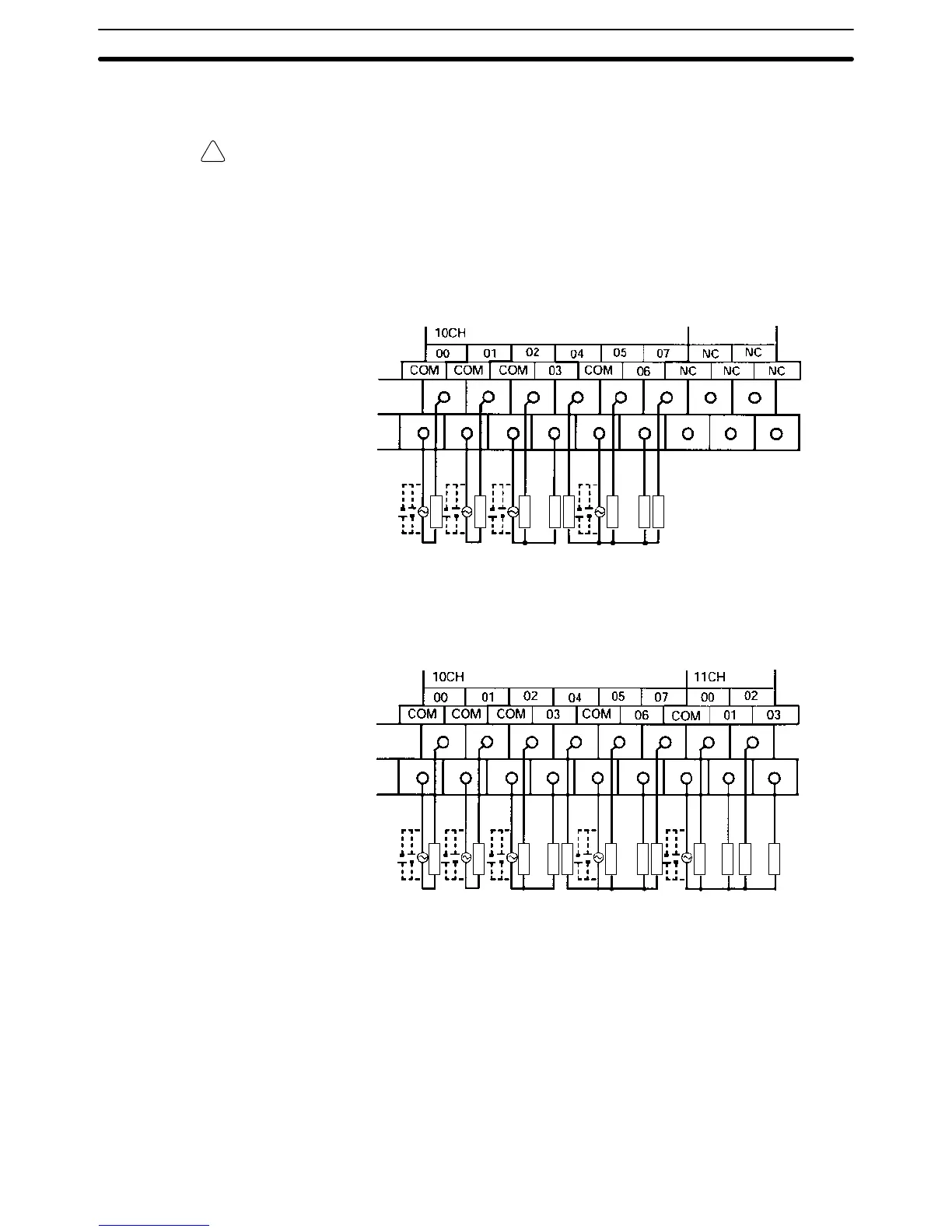
Output Configurations
CPM2A-20CDR-j
Terminals 00 through 07 of “10CH” correspond to IR 01000 through IR 01007.
250 VAC/
24 VDC
250 VAC/
24 VDC
250 VAC/
24 VDC
250 VAC/
24 VDC
Load
Load
Load
Load
Load
Load
Load
Load
CPM2A-30CDR-j
Terminals 00 through 07 of “10CH” correspond to IR 01000 through IR 01007.
Terminals 00 through 03 of “11CH” correspond to IR 01100 through IR 01103.
250 VAC/
24 VDC
250 VAC/
24 VDC
250 VAC/
24 VDC
250 VAC/
24 VDC
250 VAC/
24 VDC
Load
Load
Load
Load
Load
Load
Load
Load
Load
Load
Load
Load
Wiring and Connections
Section 3-4