11
System Configuration Section 1-3
Full Range of Functions for Handling Troubles
A full range of functions is provided for promptly handling any troubles that
may arise.
• Self-diagnostic function when power is turned ON
• Remote node connection check by PING command
• Remote node connection check by internode test
• Error log for recording error information when an error occurs
• Notification by e-mail when an error occurs
1-3 System Configuration
1-3-1 System Configuration
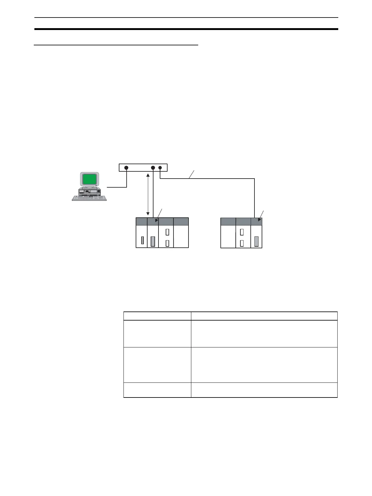
1-3-2 Devices Required for Constructing a Network
The basic configuration for a 100Base-TX Ethernet System consists of one
hub to which nodes are attached in star form using twisted-pair cable.
The devices shown in the following table are required to configure a network
with 100Base-TX-type CS1W-ETN21 and CJ1W-ETN21 Ethernet Units, so
prepare them in advance.
Recommended Hubs For details on recommended devices for constructing a network, refer to 2-4
Network Installation.
(3) Hub
CX-Programmer
CX-Integrator
FinsGateway
(2) Twisted-pair cable
100 m
max.
(1) CS1W-ETN21
Ethernet Unit
(100Base-TX)
(1) CJ1W-ETN21
Ethernet Unit
(100Base-TX)
CS-series
PLC
CJ-series
PLC
Network device Contents
(1) CS-series Ethernet
Units (CS1W-ETN21)
or CJ-series Ethernet
Units (CJ1W-ETN21)
These Ethernet Units are Communications Units that
connect a CS-series or CJ-series PLC to 100Base-TX
Ethernet networks. (They can also be used as 10Base-T.)
(2) Twisted-pair cable This is twisted-pair cable for connecting 100Base-TX-type
Ethernet Units to the hub, with an RJ45 Modular Connec-
tor at each end.
Use a category 3, 4, 5, or 5e UTP (unshielded twisted-
pair) or STP (shielded twisted-pair) cable.
(3) Hub This is a relay device for connecting multiple nodes in a
star LAN.