132
Operating Procedure Section 4-2
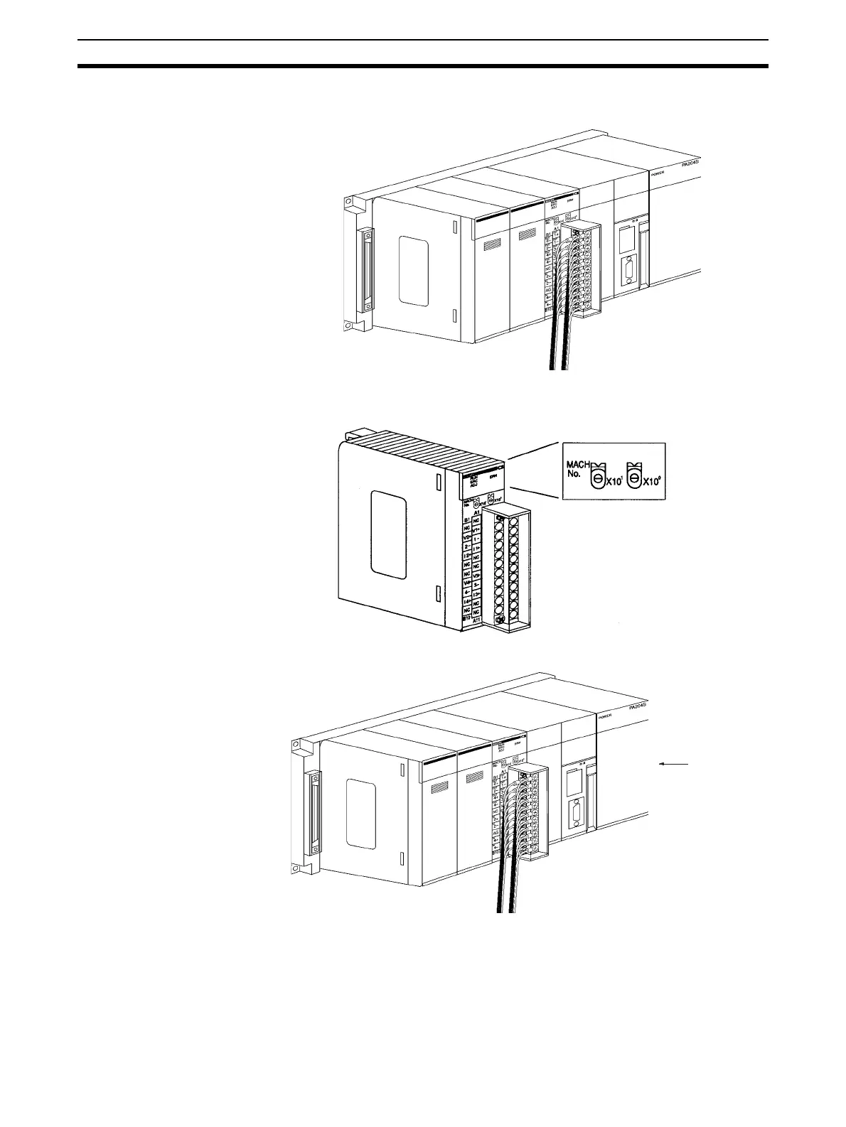
2. Mount and wire the Analog Output Unit. Refer to 1-2-1 Mounting Proce-
dure, 4-4 Wiring or 4-4-3 Output Wiring Example for further details.
3. Set the unit number switch. Refer to 4-3-2 Unit Number Switch for further
details.
4. Turn ON the power to the PLC.
If the unit number is set to 1,
words will be allocated to the
Special I/O Unit Area CIO 2010
to CIO 2019 and to the Special
I/O Unit Area D20100 to D20199.
Power ON

 Loading...


