11-2SectionSocket Applications
192
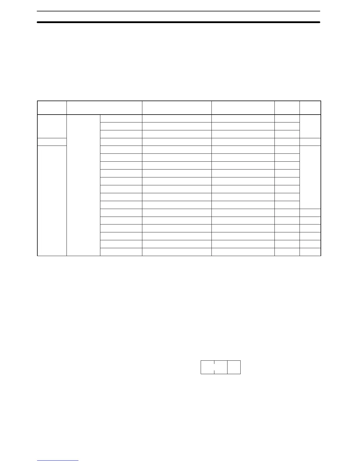
11-2-2 PC Memory Areas
The memory areas of the PC that can be specified for results storage when
executing commands from the PC are listed in the table below. The Variable type
is set in the first byte of the results storage area. The remaining three bytes con-
tain the address for communications.
Addresses in the Addresses for communications column are not the same as the
actual memory addresses.
Memory
area
Data type Word addresses Addresses for
communications
Variable
type
Bytes
Bit Areas Current
CIO CIO 0000 to CIO 6143 000000 to 17FF00 B0 (80)*
2
value of
HR H000 to H511 0A0000 to 01FF00 B2
word
A A448 to A959 0B0000 to 03BF00 B3
DM Area DM D00000 to D32767 000000 to 7FFF00 82 2
EM Area
Bank 0 E0_E00000 to E0_E32765 000000 to 7FFF00 A0 (90)*
2
Bank 1 E1_E00000 to E1_E32765 000000 to 7FFF00 A1 (91)*
Bank 2 E2_E00000 to E2_E32765 000000 to 7FFF00 A2 (92)*
Bank 3 E3_E00000 to E3_E32765 000000 to 7FFF00 A3 (93)*
Bank 4 E4_E00000 to E4_E32765 000000 to 7FFF00 A4 (94)*
Bank 5 E5_E00000 to E5_E32765 000000 to 7FFF00 A5 (95)*
Bank 6 E6_E00000 to E6_E32765 000000 to 7FFF00 A6 (96)*
Bank 7 E7_E00000 to E7_E32765 000000 to 7FFF00 A7 (97)*
Bank 8 E8_E00000 to E8_E32765 000000 to 7FFF00 A8 2
Bank 9 E9_E00000 to E9_E32765 000000 to 7FFF00 A9 2
Bank A EA_E00000 to EA_E32765 000000 to 7FFF00 AA 2
Bank B EB_E00000 to EB_E32765 000000 to 7FFF00 AB 2
Bank C EC_E00000 to EC_E32765 000000 to 7FFF00 AC 2
Current bank E00000 to E32765 000000 to 7FFF00 98 2
Note The variable types (area designations) given in parentheses can also be used,
allowing CV-series or CVM1 programs to be more easily corrected for use with
CS1-series PCs.
Word and Bit Addresses Three bytes of data are used to express data memory addresses of PCs. The
most significant two bytes give the word address and the least significant byte
gives the bit number between 00 and 15. The word address combined with the
bit number expresses the bit address. The bit number is always 00 because
Ethernet Units can handle only word data, i.e., individual bits cannot be ad-
dressed.
00
Word Bit
Word addresses for specific memory area words can be calculated by convert-
ing the normal decimal word address to hexadecimal and adding it to the first
word in the Addresses for communications column in the above table. For exam-
ple, the address for communications for D00200 would be 0000 (from above
table) plus C8 (decimal 200 converted to hexadecimal), or 00C8.
 Loading...