1-5SectionSpecifications
6
1-5 Specifications
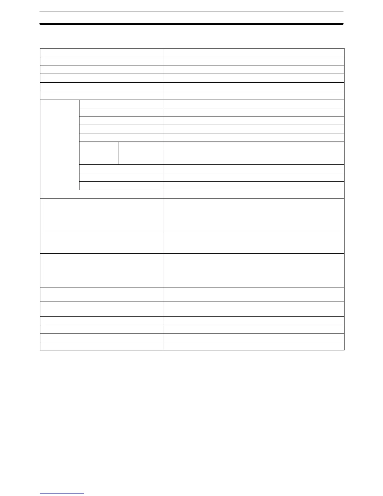
Item Specifications
Model number CS1W-ETN01
Applicable PCs CS1-series PCs
Unit classification CPU Bus Unit
Mounting location CPU Rack or Expansion Rack
Number of Units that can be mounted 4 max. (including Expansion Racks)
Transfer
Media access method CSMA/CD
specifications
Modulation Baseband
Transmission paths Bus
Baud rate 10 Mbps
Transmission media Coaxial cable
Transmission
Segment length 500 m max.
distance
Distance
between nodes
2,500 m max.
Number of connectible nodes 100/segment max.
Distance between nodes Multiples of 2.5 m
Transceiver cable length 50 m max.
Current consumption (Unit) 400 mA max. at 5 VDC
External power supply Capacity: 0.3 A min. at 24 VDC (per node)
Inrush current: 2.5 A max. (when 24-VDC startup time is 5 ms)
Permissible voltage fluctuation range:
20.4 VDC to 26.4 VDC (24 VDC –15% to +10%)
Recommended power supply: OMRON S82J-series
Power supply to transceiver Capacity: 0.4 A at 12 V
Voltage fluctuation range: 13.05 VDC to 14.48 VDC
Ripple: 2% p-p
Vibration resistance Conforms to JIS C0911.
10 to 57 Hz, 0.075-mm amplitude, 57 to 150 Hz, acceleration: 9.8
m/s
2
(1G) in X, Y, and Z directions for 80 minutes each
(Time coefficient; 8 minutes × coefficient factor 10 = total time 80
minutes)
Shock resistance Conforms to JIS C0912.
147 m/s
2
(15G) three times each in X, Y, and Z directions
Ambient temperature Operating: 0 to 55°C
Storage: –20 to 75°C
Humidity 10% to 90% (with no condensation)
Atmosphere Must be free from corrosive gas.
Weight 300 g max.
Dimensions 35 x 130 x 101 mm (W x H x D)
 Loading...