120
Loop Burnout Alarm Section 4-12
Determining the LBA
Detection Time
• To manually set the LBA detection time, set the LBA Detection Time
parameter to twice the LBA reference time given below.
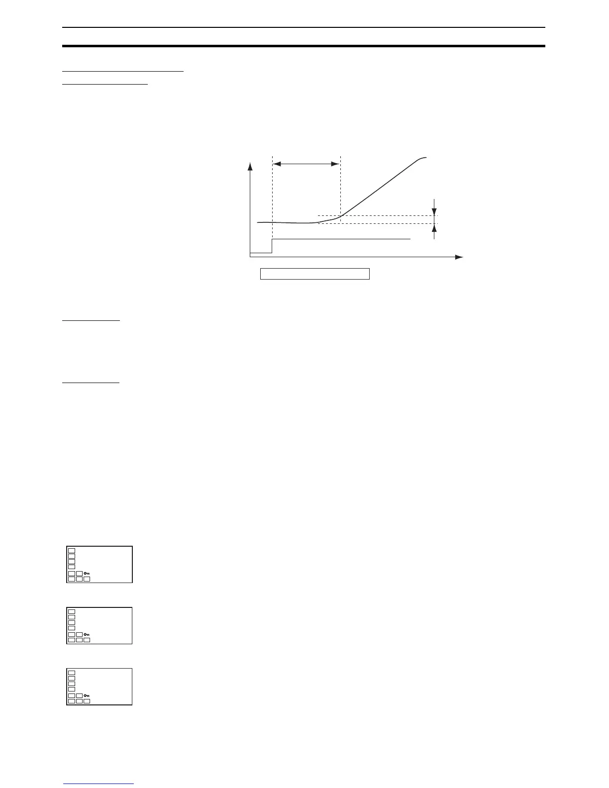
1,2,3... 1. Set the output to the maximum value.
2. Measure the time required for the width of change in the input to reach the
LBA band.
3. Set the LBA Detection Time parameter to two times the measured time.
LBA Level • Set the control deviation when the control loop is working properly.
• The default is 8.0 (°C/°F) for Controllers with Thermocouple/Resistance
Thermometer Universal Inputs and 10.00% FS for Controllers with Analog
Inputs.
LBA Band • There is assumed to be an error in the control loop if the control deviation
is greater than the threshold set in the LBA Level parameter and if the
control deviation does not change by at least the value set in the LBA
Band parameter.
• The default is 3.0 (°C/°F) for Controllers with Thermocouple/Resistance
Thermometer Universal Inputs and 0.20% FS for Controllers with Analog
Inputs.
Operating Procedure Perform the following procedure to use the loop burnout alarm.
In this example, the LBA detection time is set to 10, the LBA level is set to 8.0,
and the LBA band is set to 3.0.
MV = 100%
PV
Temperature
Time
Measurement time
Tm
LBA band
LBA detection time = Tm × 2
Operation Level
Initial Setting Level
1. Press the O Key for at least three seconds to move from the operation
level to the initial setting level.
Initial Setting Level
2. Select the Alarm 1 Type parameter by pressing the M Key.
C
25
100
PV/SP
in-t
5
Input Type
alt1
2
Alarm 1 Typ