35
Wiring Terminals Section 2-2
• Recommended Ferrules for SUB2 on E5GN
Note Do not remove the terminal block from the E5AN, E5EN, or E5CN. Doing so
may cause product malfunction or incorrect operation.
2-2-3 Wiring
In the connection diagrams, the left side of the terminal numbers represents
the inside of the Controller and the right side represents the outside.
Power supply • With the E5CN, connect to terminals 9 and 10; with the E5CN-U, connect
to pins 10 and 11; with the E5AN, E5EN, and E5GN, connect pins 1 and
2. The following table shows the specifications.
• These models have reinforced insulation between the input power supply,
the relay outputs, and other terminals.
Manufacturer Model number
Phoenix Contact AI 0,25-6 BU
AI 0,34-6 TQ
AI 0,5-6 WH
AI 0,75-6 GY
AI 1-6 RD
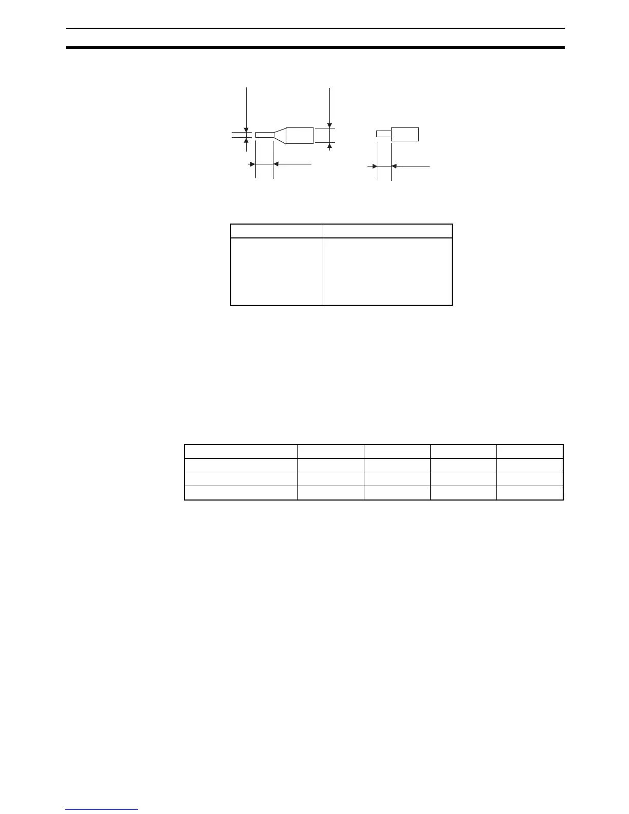
Ferrules Wires
0.8 to 1.5 mm
6 mm
6 mm
3 mm max.
Input power supply E5CN E5CN-U E5AN/EN E5GN
100 to 240 VAC, 50/60 Hz 7.5 VA 6 VA 10 VA 5.5 VA
24 VAC, 50/60 Hz 5 VA 3 VA 5.5 VA 3 VA
24 VDC (no polarity) 3 W 2 W 4 W 2 W