40
Wiring Terminals Section 2-2
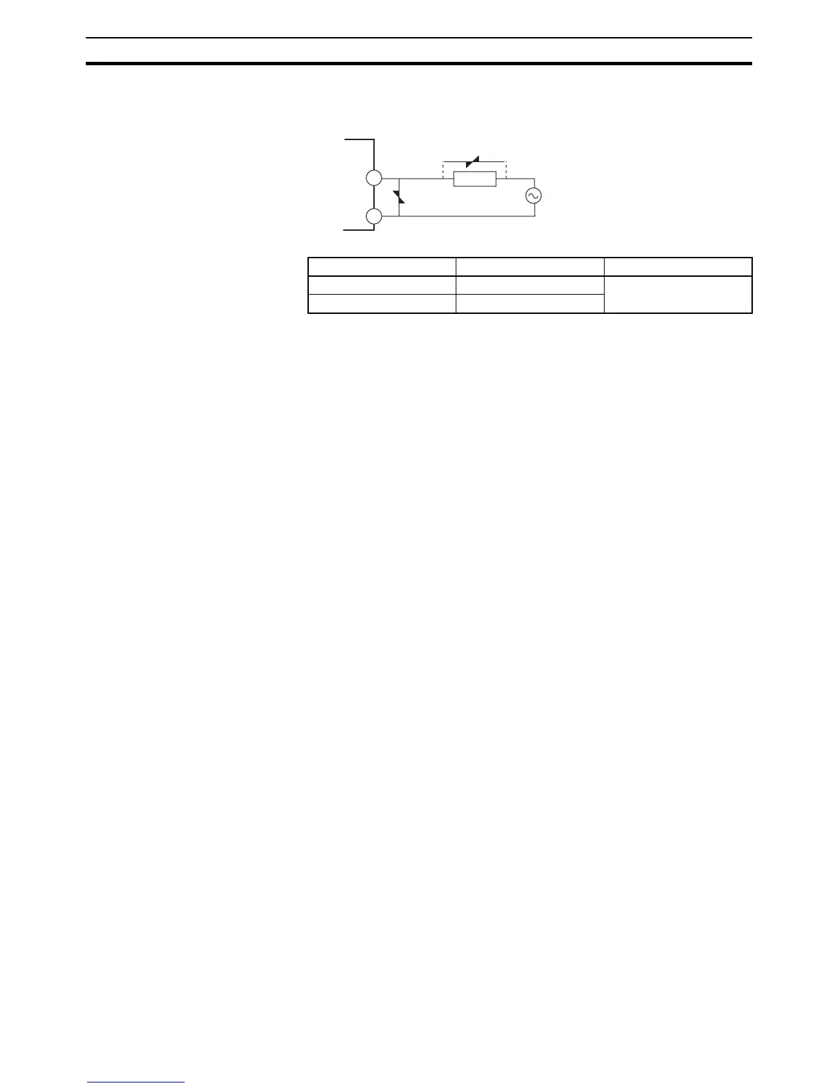
• Take countermeasures such as installing a surge absorber. As an addi-
tional safety measure, provide error detection in the control loop. (Use the
Loop Burnout Alarm (LBA) and HS alarm that are provided for the E5@N.)
Select a surge absorber that satisfies the following conditions.
Auxiliary Outputs 1, 2, and
3
• On the E5CN-@2@@@, auxiliary output 1 (SUB1) is output across termi-
nals 7 and 8, and auxiliary output 2 (SUB2) is output across terminals 6
and 8.
• On the E5CN-@1@@@U, auxiliary output 1 (SUB1) is output across termi-
nals 7 and 8.
• On the E5CN-@2@@@U, auxiliary output 1 (SUB1) is output across termi-
nals 7 and 8, and auxiliary output 2 (SUB2) is output across terminals 7
and 9.
• On the E5AN/EN-@3@@@, auxiliary output 1 (SUB1) is output across ter-
minals 9 and 10, auxiliary output 2 (SUB2) is output across terminals 7
and 8, and auxiliary output 3 (SUB3) is output across terminals 5 and 6.
• On the E5GN-@2@@@, auxiliary output 1 (SUB1) is output across termi-
nals 5 and 6, and auxiliary output 2 (SUB2) is output across terminals 13
and 14 on the bottom of the Controller. Wire terminals 13 and 14 and
tighten the screws.
• When the Input Error Output parameter is set to ON, the output assigned
to the alarm 1 function turns ON when an input error occurs.
• When the HB alarm, HS alarm, or heater overcurrent alarm is used with
the E5CN-@@H@, E5CN-@@HH@, or E5GN-@@H@, alarms are output to
the output assigned to the alarm 1 function.
• When the HB alarm, HS alarm, or heater overcurrent alarm is used with
the E5AN/EN-@@H@@, alarms are output to the output assigned to the
alarm 1 function.
• On the E5CN and E5CN-U, when heating/cooling control is used, auxil-
iary output 2 becomes control output (cooling).
• On the E5AN and E5EN, when heating/cooling control is used, auxiliary
output 3 becomes control output (cooling).
• On the E5GN, when heating/cooling control is used, auxiliary output 1
becomes control output (cooling).
• For models that have a heater burnout alarm, an OR of the alarm 1 func-
tion and the HB alarm, HS alarm, or heater overcurrent alarm is sent to
the output assigned to the alarm 1 function (auxiliary output 1). If the
alarm 1 function is to be used for HB alarm only, set the alarm 1 type to 0
(i.e., do not use alarm 1 function).
• The following diagrams show the internal equalizing circuits for auxiliary
outputs 1, 2, and 3.
Voltage used Varistor voltage Surge resistance
100 to 120 VAC 240 to 270 V 1,000 A min.
200 to 240 VAC 440 to 470 V
1
2
Long-life
relay output
Varistor
Varistor
Inductive
load