14 Digital Temperature Controllers E5CN/E5CN-U
Operation
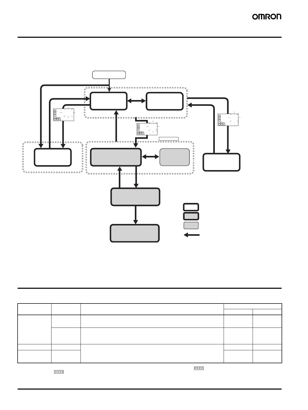
■ Outline of Operation Procedures
The following diagram illustrates the entire setting level. A password is required to enter the advance function setting level and the calibration level.
Some parameters may not be displayed depending on the protection settings and operation conditions.
The control operation will stop when switching from operation level to initial setting level.
]
Note: 1. Operation level entered for software reset.
2. You cannot move to other levels by operating the keys on the front panel from the calibration level. You must turn OFF the power supply.
3. You can move only to the operation level by operating the keys on the front panel from the manual control level.
4. The time taken to move to the protect level can be adjusted by changing the “Move to protect level time” setting.
Troubleshooting
If an error occurs, an error message will be displayed on the No. 1 display. Use the error message to check the type of error and correct the error
accordingly.
Note: 1. If the input exceeds is within the controllable range but exceeds the display range (−1999 to 9999), will be displayed if the temperature is less than
−1999 and will be displayed if the temperature is more than 9999. The control and alarm outputs will function normally during these displays. Refer
to the E5CN/E5CN-U Temperature Controller User's Manual (Cat. No. H129) for information on the controllable range.
2. These errors are displayed only when the PV/SP is displayed. Errors are not displayed in other display modes.
No. 1 display Error Correction Output status at error
Control outputs Alarm outputs
s.err (S. Err) Input error
(See note 2.)
Check for input wiring errors, broken wires, short-circuits, and input type error. OFF Handled as
abnormally high
temperature
A/D converter
error
(See note 2.)
Check for an input error and then cycle the power supply. If the same error is still
displayed, repairs will be necessary.
If the Temperature Controller is normal after cycling the power supply, the error may have
been caused by noise. Check for noise being generated nearby.
OFF OFF
e111 (E111) Memory error Cycle the power supply. If the same error is still displayed, repairs will be necessary.
If the Temperature Controller is normal after cycling the power supply, the error may have
been caused by noise. Check for noise being generated nearby.
OFF OFF
h.err (H. Err) Internal circuit
error
(See note 2.)
OFF OFF
Input password.
Input password.
Set value 1201
Control in progress
Control stopped
Operation Level
Not displayed for some models
Level change
Initial Setting Level
Communications
Setting Level
Adjustment Level
Protect Level
Power ON
Press the
Level Key
less than 1 s.
Manual
Control Level
Press the Level
Key for at least 1 s.
Starting in manual mode
Starting in automatic mode
Manual
Mode
Press the Level
Key for at least 1 s.
Press the
Level + Mode
Keys.
for at least 1 s
Calibration Level
Press the
Level + Mode Keys;
display will flash.
Advanced Function
Setting Level
(See
note 1.)
(See
note 2.)
(See
note 3.)
a-m
C
25
100
C
25
100
C
Set value −169
Press the Level Key
for at least 3 s while
a-m is displayed.
Press the Level Key
for at least 1 s;
display will flash.
Press the
Level Key for
at least 1 s.
Press the Level Key
for at least 1 s;
display will flash.
Press the Level Key for
at least 3 s.
Control stops .
Press the Level +
Mode Keys for at least
3 s. (See note 4.)
Press the Level Key
for less than 1 s.