16 Digital Temperature Controllers E5CN/E5CN-U
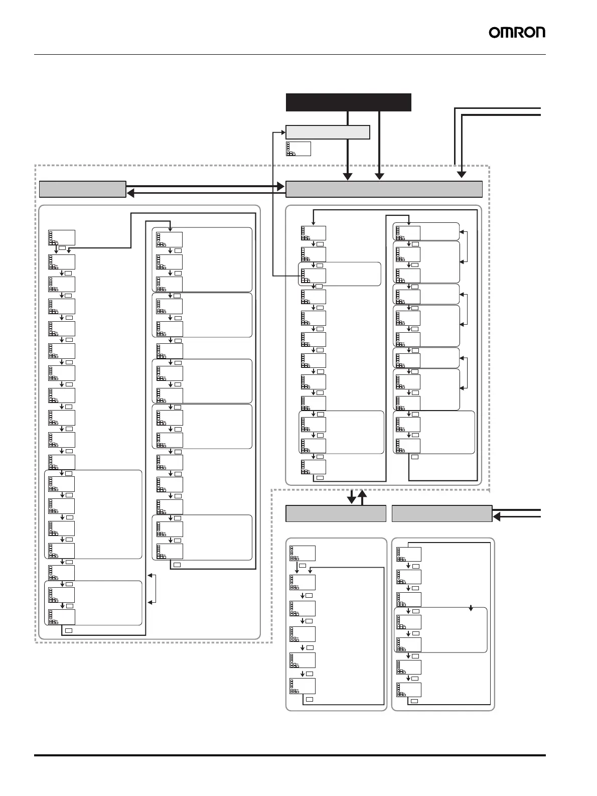
■ Parameters
Operation Level
Manual Control Level
Power ON
Adjustment Level
Protect Level
Communications
Setting Level
a-m
m-sp
0
25
C
25
0
C
sp-m
0
C
ct1
0.0
ct2
0.0
lcr1
0.0
lcr2
0.0
prst
rset
sktr
0
r-s
run
al-1
0
C
al1h
0
C
al1l
0
C
al-2
0
C
al2h
0
C
al2l
0
C
al-3
0
C
al3h
0
C
al3l
0
C
o
0.0
c-o
0.0
Process value
Added when PV
display is added.
Process value/
set point
Multi-SP set
point setting
SP ramp monitor
Heater current value 1
monitor
Heater current value 2
monitor
Leakage current
value 1 monitor
Leakage current
value 2 monitor
Program start
Remaining soak
time monitor
Run/stop
Alarm value 1
Upper-limit
alarm value 1
Lower-limit
alarm value 1
Alarm value 2
Upper-limit
alarm value 2
Lower-limit
alarm value 2
Alarm value 3
Upper-limit
alarm value 3
Lower-limit
alarm value 3
MV monitor (heating)
MV monitor (cooling)
cmwt
off
ct1
0.0
l.adj
at
off
ct2
0.0
lcr1
0.0
lcr2
0.0
hb1
0.0
hb2
0.0
hs1
50.0
hs2
50.0
sp-0
0
C
sp-1
0
C
sp-2
0
C
sp-3
0
C
ins
0.0
C
insh
0.0
C
p
8.0
C
i
233
d
40
c-sc
1.00
c-db
0.0
C
of-r
50.0
hys
1.0
C
chys
1.0
C
soak
1
wt-b
off
C
mV-s
0.0
mV-e
0.0
sprt
off
C
ol-h
105.0
ol-l
-5.0
AT execute/cancel
Communications writing
SSR failure detection 1
SSR failure detection 2
SP 0
SP 1
SP 2
SP 3
Temperature input shift
Proportional band
Integral time
Derivative time
Cooling coefficient
Dead band
Manual reset value
Hysteresis (heating)
Hysteresis (cooling)
Soak time
Wait band
MV at stop
MV at PV error
SP ramp set value
MV upper limit
MV lower limit
Protocol setting
Communications
Unit No.
Baud rate
Data bits
Stop bits
Communications
parity
Send delay
psel
cwf
u-no
1
bps
9.6
len
7
sbit
2
prty
eVen
sdwt
20
pmoV
0
oapt
0
icpt
1
wtpt
off
pmsk
on
prlp
0
Move to protect level
Operation/adjustment
protection
Initial Setting/
Communications Protection
Setting change protection
Parameter mask enable
Password to move to
protect level
Password setting
Press the Level Key less than 1 s.
Press the Level Key less than 1 s.
Press the Level Key for at least 3 s.
(
Display flashes for at least 1 s.)
Displays other than that for switching
between automatic and manual
Starting in automatic
mode
Starting in manual mode
25
C
PV/MV
PID control only
insl
0.0
C
SP used by multi-SP
Set either of these parameters.
PID settings
Heating/cooling
Hysteresis settings
1-point shift
2-point shift
CompoWay/F
(SYSWAY) only
Auto/manual switch
PID control only
Added when auto/manual
switching function is added.
Set either of these parameters.
Press the
Level Key
for at
least 1 s.
Adjustment level
display
Displayed only once when
entering adjustment level.
a
Heater current value 1
monitor
Heater current value 2
monitor
Leakage current value
1 monitor
Leakage current value
2 monitor
Heater burnout 1
detection
Heater burnout 2
detection
Upper-limit
temperature input
Lower-limit
temperature input
Clear the offset during stabilization
of P or PD control.
Press the
Level
Key for at
least 3 s.
(Display
flashes
for at
least 1 s.)
Set either of these parameters.Set either of these parameters.
Press the Level + Mode
Keys for at least 3 s.
Display flashes.
The time taken to move to the protect level can
be adjusted by changing the "Move to protect
level time" setting.
Displayed only when a password
is set. Restricts moving to protect
level.
Restricts displaying and modifying
menus in operation, adjustment,
and manual control levels.
This protect level restricts movement
to the initial setting, communications
setting, and advanced function
setting levels.
Protects changes to setups by
operating the front panel keys.
Displayed only when a
parameter mask is set.
Switches between
CompoWay/F
(SYSWAY) and Modbus.
Displayed only for models with communications.
Changes are effective after cycling power or after
a software reset.
Press the Level + Mode
Keys for at least 1 s.
Press the Level Key
less than 1 s.
a
a
a
a
a
a
a
a
a
a
a
a
a
a
a
a
a
a
a
a
a
a
a
a
a
a
a
a
a
a
a
a
a
a
a
a
a
a
a
a
a
a
a
a
a
a
a
a
a
a
a
a
a
a
a
a
a
a
a
a
a
a
a
a
a
a
a
a
Some parameters are not displayed depending on the
model of the Controller and parameter settings. For details,
refer to the E5CN/E5CN-U Temperature Controller User's
Manual (Cat. No. H129)
 Loading...


