Digital Temperature Controllers E5CN/E5CN-U 23
3. When starting operation after the Temperature Controller has
warmed up, turn OFF the power and then turn it ON again at the
same time as turning ON power for the load. (Instead of turning
the Temperature Controller OFF and ON again, switching from
STOP mode to RUN mode can also be used.)
4. Avoid using the Controller in places near a radio, television set, or
wireless installing. These devices can cause radio disturbances
which adversely affect the performance of the Controller.
USB-Serial Conversion Cable
1. The disk that is included with the Conversion Cable is designed
for a computer CD-ROM driver. Never attempt to play the disk in a
general-purpose audio player.
2. Do not connect or disconnect the Conversion Cable connector
repeatedly over a short period of time. The computer may
malfunction.
3. After connecting the Conversion Cable to the computer, check the
COM port number before starting communications. The computer
requires time to recognize the cable connection. This delay does
not indicate failure.
4. Do not connect the Conversion Cable through a USB hub. Doing
so may damage the Conversion Cable.
5. Do not use an extension cable to extend the Conversion Cable
length when connecting to the computer. Doing so may damage
the Conversion Cable.
Mounting
Mounting to a Panel
1. To mount the Controller so that it is waterproof, insert the
waterproof packing onto the Controller. Group mounting does not
allow waterproofing. The waterproof packing is not required if
waterproofing is not necessary.
The Panel Mounting Adapter is also included with the E5CN-U.
Waterproof packing is not included with the E5CN-U.
2. Insert the E5CN/E5CN-U into the mounting hole in the panel.
3. Push the adapter along the Controller body from the terminals up
to the panel, and fasten it temporarily.
4. Tighten the two fixing screws on the adapter. Alternately tighten
the two screws a little at time to keep them balanced. Tighten
them to a torque of 0.29 to 0.39 N·m.
Attaching the Terminal Cover
Make sure that the “UP” letters on the E5CN are at the top and insert
the terminal cover into the holes at the top and bottom of the
Controller.
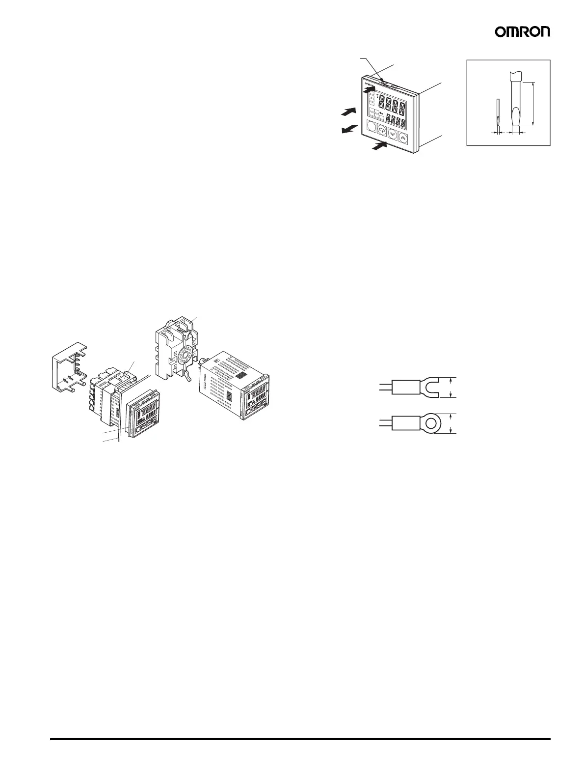
Removing the Controller from the Case
When carrying out maintenance on the Controller, the Controller can
be removed from the case with the terminal leads still attached. The
Controller can be removed from the case only with the E5CN. It
cannot be removed with the E5CN-U.
1. Insert the tool into the slots (one on the top and one on the
bottom) and release the hooks.
2. Insert the tool into the gap between the front panel and rear case
and pull out the front panel slightly. Hold both sides of the front
panel and draw out the Controller towards you. Do not apply
unnecessary force.
3. Before inserting the Controller, confirm that the sealing rubber is
in place. Insert the Controller into the rear case until you hear a
click. Press on the hooks on the top and bottom of the rear case
to be sure that the hooks are securely locked in place.Be sure
that electronic parts do not come in contact with the case.
Wiring Precautions
• Separate input leads and power lines to protect the Controller and
its lines from external noise.
• Use wires of a thickness of AWG24 (0.205 mm
2
) to AWG14
(2.081 mm
2
).
The exposed current-carrying part to be inserted into terminals
must be 5 to 6 mm.
• We recommend using crimp terminals when wiring the terminals.
• Tighten terminal screws to a torque of 0.74 to 0.90 N·m.
• Use the following type of crimp terminals for M3.5 screws.
Terminal Cover
(order separately)
Mounting Adapter
(Accessory)
E5CN
E5CN-U
Waterproof packing
Panel
Order the P2CF-11 or P3GA-11
Socket separately.
Front-mounting Socket
(Panel mounting is also possible.)
20 min.
0.4
2.0
E
5
C
N
PV
SV
AL
M
1
A
LM
2
A
LM
3
H
A
O
U
T
1
S
TO
P
O
U
T
2
C
M
W
M
AN
U
(1)
(1)
(2)
(3)
Tool insertion hole
Flat-blade screwdriver
(Unit: mm)
7.2 mm min.
7.2 mm min.
 Loading...


