10 Digital Temperature Controllers E5CN/E5CN-U
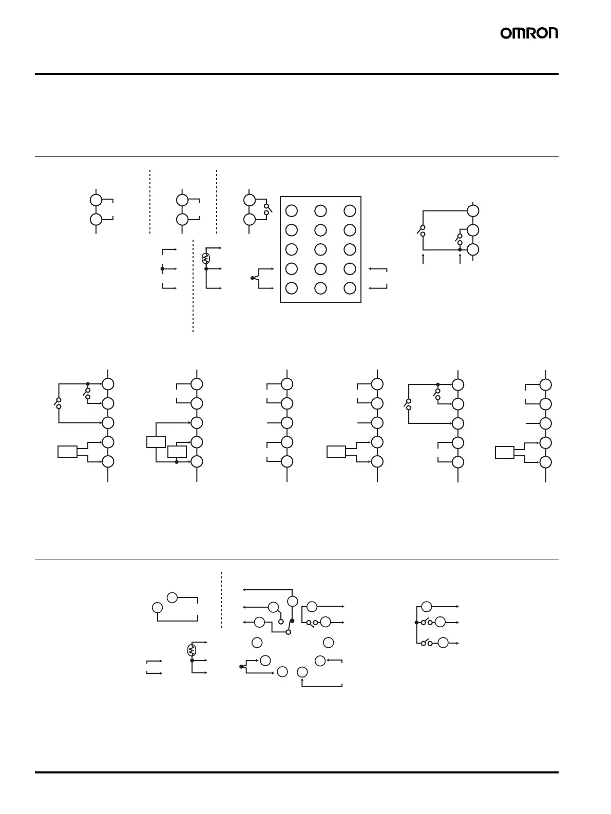
External Connections
• A voltage output (control output) is not electrically insulated from the internal circuits. When using a grounding thermocouple, do not connect
any of the control output terminals to ground. If the control output terminals are connected to ground, errors will occur in the measured
temperature values as a result of leakage current.
• Standard insulation is applied between any of the following: power supply terminals, input terminals, output terminals, and communications
terminals (for models with communications). If reinforced insulation is required, provide additional insulation, such as spacial distance or
material insulation, as defined by IEC 60664 suitable for the maximum operating voltage.
• Consult with your OMRON representative before using the external power supply for the ES1B for any other purpose.
Relay Output
Voltage Output
Terminals 11 to 15 do not exist on models without an Option Unit (heater burnout detection, control output 2, event inputs, or communications).
Terminal a
lications de
end on the model of the O
tion Unit. Refer to
a
e 3.
−
+
+
−
+
Alarm Outputs
Control output 1
Alarm 1/
Heater burnout alarm/
Input error output (See note.)
Alarm 2
Analog input
Current Output
Infrared
temperature
sensor
Communications/
Heater burnout/
SSR failure
detection (2-CT input)
Platinum
resistance
thermometer
Communications/
voltage output
specification
+
−
Do not
use.
Voltage output/
Heater burnout/
SSR failure
detection
+
−
Do not
use.
Event input 1
Event input 2
Event inputs/
Heater burnout /
SSR failure
detection
Heater burnout/
SSR failure
detection input
Heater burnout/
SSR failure
detection input
Voltage output
12 VDC, 21 mA
Heater burnout/
SSR failure
detection input
The input power supply depends on the power
supply specification of the Controller and is either
100 to 240 VAC or 24 VAC/DC (no polarity).
Note: Output when an input error output is enabled
in the Advance Function Setting Level. If an
input error output is enabled, the a1-1
operation indication on the front panel will
not light and s.err will be displayed on the
No. 1 display.
6
7
8
9
10
11
12
13
14
15
1
3
2
4
5
11
12
13
14
15
B
Pt
TC
A
B
B
A
V
mA
6
7
8
1
2
1
2
1
2
RS-485
CT1
CT2
11
12
13
14
15
B
A
RS-485
11
12
13
14
15
11
12
13
14
15
CT1 CT1
−
+
4 to 20 mA DC/
0 to 20 mA DC
−
+
12 VDC
21 mA
Input power supply
Control output 2
Voltage output
12 VDC, 21 mA
Control output 2
11
12
13
14
15
Event input 1
Event input 2
Event inputs/
External power
supply for ES1B
12 VDC±10%
20 mA
11
12
13
14
15
External power suppl
for ES1B and Heater
burnout/SSR failure
detection
+
−
External power
12 VDC±10%
20 mA
External power
Do not
use.
CT1
Heater burnout/
SSR failure
detection input
+
−
E5CN
7
8
9
10
11
1
2
3
4
6
Voltage Output
Pt TC
Alarm 1/
Input error output
(See note.)
Control output 1
Input power supply
Do not use.
7
8
9
Alarm 1/
Input error output
Alarm 2/
Control output 2
Analog input
A
B
B
+
+
+
−
−
−
DC12V
21mA
5
4
Relay Output
One Alarm Output Two Alarm Outputs
5
Infrared temperature sensor
Platinum
resistance
thermometer
The input power supply depends on the power supply specification of the
Controller and is either 100 to 240 VAC or 24 VAC/DC (no polarity).
Order the P2CF-11 or P3GA-11 Socket separately. (See page 13.)
Note: Output when an input error output is
enabled in the Advance Function
Setting Level. If an input error
output is enabled, the al-1
operation indication on the front
panel will not light and s.err will be
displayed on the No. 1 display.
0 to 50 mV input only
E5CN-U