Digital Temperature Controllers E5CN/E5CN-U 17
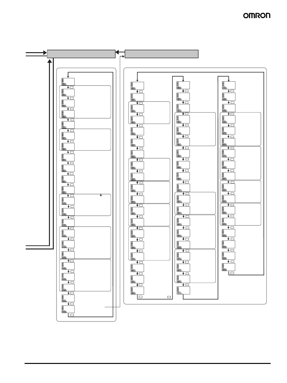
Initial Setting Level
Advanced Function Setting Level
in-l
0
dp
0
in-t
5
in-h
100
d-u
c
sl-h
1300
C
sl-l
-200
C
cntl
onof
s-hc
stnd
st
on
ptrn
off
cp
20
c-cp
20
oreV
or-r
alt1
2
alt2
2
alt3
2
tr-t
off
tr-h
100.0
tr-l
0.0
o1-t
4-20
amoV
0
Input type
Scaling upper limit
Scaling lower limit
Decimal point
Temperature unit
SP upper limit
SP lower limit
PID ON/OFF
Standard or heating/ cooling
ST
Program
pattern
Control period (heating)
Control period (cooling)
Direct/reverse operation
Alarm 1 type
Alarm 2 type
Alarm 3 type
Transfer output type
Transfer output upper limit
Transfer output lower limit
Linear current output
init
off
eV-m
1
eV-1
none
eV-2
stop
mspu
off
spru
m
rest
a
al1n
n-o
alh1
0.2
C
al2n
n-o
alh2
0.2
C
al3n
n-o
alh3
0.2
C
hbu
on
hbl
off
hbh
0.1
st-b
15.0
C
alfa
0.65
inf
0.0
pVad
off
o-dp
off
ret
off
a1lt
off
a2lt
off
a3lt
off
prlt
3
sero
off
cjc
on
rlrV
off
colr
red
pV-b
5.0
C
a1on
0
a2on
0
a3on
0
a1of
0
a2of
0
a3of
0
istp
ins1
mVse
off
amad
off
rt
off
hsu
on
hsl
off
hsh
0.1
lba
0
lbal
8.0
C
lbab
3.0
C
out1
o
out2
none
alm1
alm1
alm2
alm2
csel
on
t-u
m
alsp
sp-m
cmoV
0
Parameter
initialization
Number of multi-SP
uses
Event input
assignment 1
Event input
assignment 2
Multi-SP uses
SP ramp time unit
Alarm 1 open in
alarm
Alarm 1 hysteresis
Alarm 2 open in
alarm
Alarm 2 hysteresis
Alarm 3 open in
alarm
Alarm 3 hysteresis
Heater burnout
detection
Heater burnout latch
ST stable range
α
Input digital filter
Additional PV
display
MV display
Automatic return of
display mode
Alarm 1 latch
Alarm 2 latch
Alarm 3 latch
Move to protect level time
Input error output
Cold junction
compensating method
MB command logic
switching
PV display color
PV stable range
Alarm 1 ON delay
Alarm 2 ON delay
Alarm 3 ON delay
Alarm 1 OFF delay
Alarm 2 OFF delay
Alarm 3 OFF delay
Input shift type
Additional MV for
stop/error
RT
SSR failure
detection
SSR failure latch
SSR failure
hysteresis
LBA detection time
LBA detection
threshold
LBA detection
width
Control output 1
assignment
Control output 2
assignment
Alarm output 1
assignment
Alarm output 2
assignment
Display text switch
Soak time unit
Alarm SP selection
Move to calibration
level
Press the Level Key less than 1 s.
Move by setting password (−169).
Press the Level Key for at least 1 s.
Two SPs: 1
Four SPs: 2
For input type of analog
Limit the set point.
Set the pulse output cycle.
Linear output
Linear output
°C, °F
a
For input type of
temperature
For input type of
temperature,
standard, or PID
When assigning PID
or control output to
pulse output
Displayed when initial setting/
communications protection is set to 0
Move to advanced
function setting level
Heater burnout
hysteresis
Standby sequence
reset method
Auto/manual
switching function
addition
a
a
a
a
a
a
a
a
a
a
a
a
a
a
a
a
a
a
a
a
a
a
a
a
a
a
a
a
a
a
a
a
a
a
a
a
a
a
a
a
a
a
a
a
a
a
a
a
a
a
a
a
a
a
a
a
a
a
a
a
a
a
a
a
a
a
a
a
a
a
a
a
a
a
a
a
 Loading...


