Digital Temperature Controllers E5CN/E5CN-U 7
■ Alarm Types
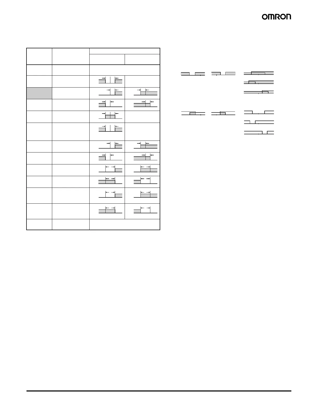
Select alarm types out of the 12 alarm types listed in the following table.
Note: 1. With set values 1, 4 and 5, the upper and lower limit values
can be set independently for each alarm type, and are
expressed as “L” and “H.”
2. Set value: 1, Upper- and lower-limit alarm
3. Set value: 4, Upper- and lower-limit range
4. Set value: 5, Upper- and lower-limit with standby sequence
For Upper- and Lower-Limit Alarm Described Above
• Case 1 and 2
Always OFF when the upper-limit and lower-limit
hysteresis overlaps.
• Case 3: Always OFF
5. Set value: 5, Upper- and lower-limit with standby sequence
Always OFF when the upper-limit and lower-limit hysteresis
overlaps.
6. Set value: 12, LBA can be set only for alarm 1.
Set the alarm types for alarms 1 to 3 independently in the initial
setting level. The default setting is 2 (upper limit).
Set value Alarm type Alarm output operation
When X is
positive
When X is
negative
0 Alarm function
OFF
Output OFF
1
(See note 1.)
Upper- and lower-
limit
(See note 2.)
2 Upper limit
3Lower limit
4
(See note 1.)
Upper- and lower-
limit range
(See note 3.)
5
(See note 1.)
Upper- and lower-
limit with standby
sequence
(See note 5.)
(See note 4.)
6 Upper-limit with
standby sequence
7 Lower-limit with
standby sequence
8 Absolute-value
upper-limit
9 Absolute-value
lower-limit
10 Absolute-value
upper-limit with
standby sequence
11 Absolute-value
lower-limit with
standby sequence
12
(See note 6.)
LBA (for alarm 1
only)
---
ON
OFF
SP
LH
SP
X
ON
OFF
SP
X
ON
OFF
SP
X
ON
OFF
SP
X
ON
OFF
SP
LH
ON
OFF
SP
LH
ON
OFF
SP
X
ON
OFF
SP
X
ON
OFF
SP
X
ON
OFF
SP
X
ON
OFF
0
X
ON
OFF
0
X
ON
OFF
0
X
ON
OFF
0
X
ON
OFF
0
X
ON
OFF
0
X
ON
OFF
0
X
ON
OFF
0
X
ON
OFF
LH
H<0, L>0
|H| < |L|
SP
Case 1
LH
H>0, L<0
|H| > |L|
SP
Case 2
LH
H<0, L<0
SP
LH
H<0, L>0
|H| ≥ |L|
SP
LH
H>0, L<0
H
≤
L
SP
Case 3 (Always ON)
LH
H<0, L>0
|H| < |L|
SP
Case 1
LH
H>0, L<0
|H| > |L|
SP
Case 2
LH
H<0, L<0
SP
L
L
H
H<0, L>0
|H| ≥ |L|
SP
H
H>0, L<0
|H| ≤ |L|
SP
Case 3 (Always ON)