Digital Temperature Controllers E5CN/E5CN-U 9
■ Current Transformer
(Sold Separately)
Ratings
■ Heater Burnout Alarms and SSR
Failure Detection Alarms
(E5CN Models with Heater Burnout and SSR Failure Detection
Alarms)
Note: 1. If the ON time of control output 1 is less than 190 ms, heater
burnout detection and the heater current will not be
measured.
2. If the OFF time of control output 1 is less than 190 ms, SSR
failure detection and the heater current will not be
measured.
■ Electrical Life Expectancy
Curve for Relays
(Reference Values)
Note: Do not connect a DC load to a Controller with a Long-life Relay
Output.
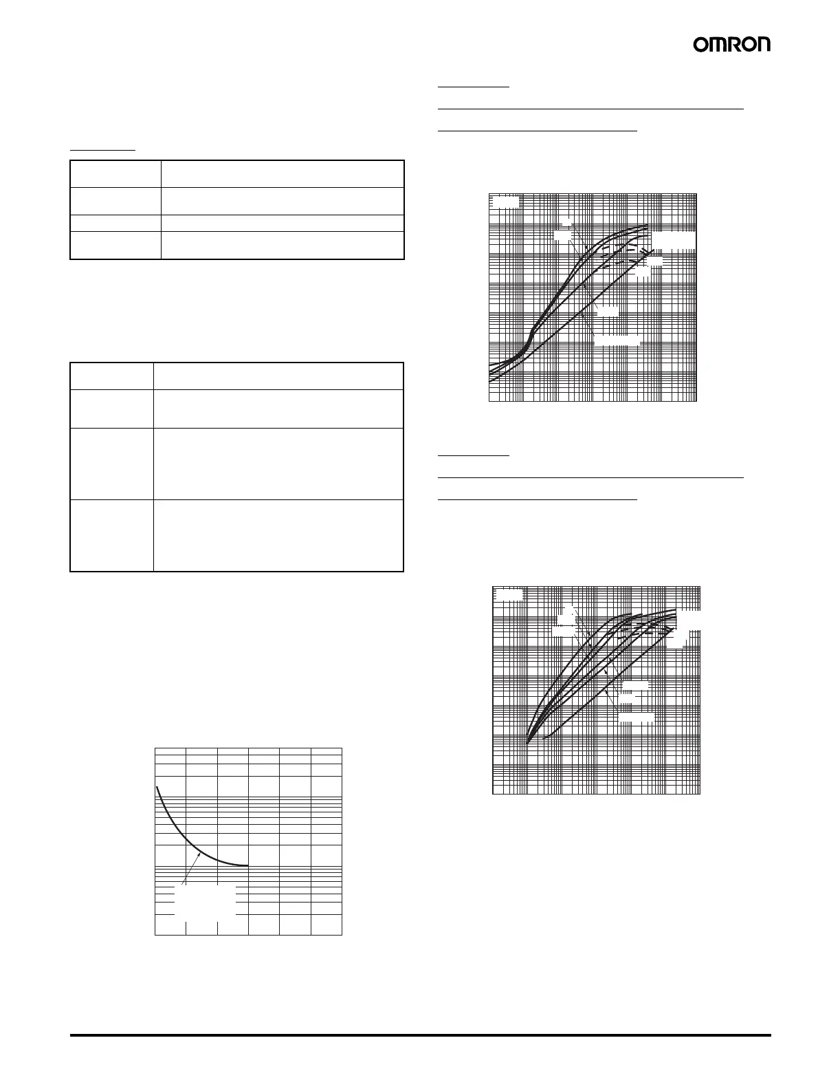
E54-CT1
Thru-current (Io) vs. Output Voltage
(Eo) (Reference Values)
Maximum continuous heater current: 50 A (50/60 Hz)
Number of windings: 400±2
Winding resistance: 18±2
Ω
E54-CT3
Thru-current (Io) vs. Output Voltage
(Eo) (Reference Values)
Maximum continuous heater current: 120 A (50/60 Hz)
(Maximum continuous heater current for an OMRON Temperature
Controller is 50 A.)
Number of windings: 400±2
Winding resistance: 8±0.8
Ω
Dielectric
strength
1,000 VAC for 1 min
Vibration
resistance
50 Hz, 98 m/s
2
Weight E54-CT1: Approx. 11.5 g, E54-CT3: Approx. 50 g
Accessories
(E54-CT3 only)
Armatures (2)
Plugs (2)
Maximum
heater current
50 A AC
Input current
indication
accuracy
±5% FS ±1 digit max.
Heater burnout
alarm setting
range
0.1 to 49.9 A (in units of 0.1 A)
0.0 A: Heater burnout/SSR failure alarm output
turned OFF.
50.0 A: Heater burnout/SSR failure alarm output
turned ON.
Minimum detection ON time: 190 ms (See note 1.)
SSR failure
detection
alarm setting
range
0.1 to 49.9 A (in units of 0.1 A)
0.0 A: Heater burnout/SSR failure alarm output
turned ON.
50.0 A: Heater burnout/SSR failure alarm output
turned OFF.
Minimum detection OFF time: 190 ms (See note 2.)
500
300
100
50
30
10
5
3
1
0123456
Switching current (A)
Life (
×
10
4
operations)
E5CN
250 VAC, 30 VDC
(resistive load)
cosφ = 1
1 10 100 mA 1 10 100
1,000 A
100 V
3%
1%
100 Ω
∞
10
1
100 mV
10
1
100 µV
10
1 kΩ
RL = 10 Ω
Distortion
factor 10%
50 Hz
Output voltage (Eo) V (r.m.s.)
Thru-current (Io) A (r.m.s.)
1 10 100 mA 1 10 100
1,000 A
100 V
3%
1%
1 kΩ
100 Ω
50 Ω
RL = 10 Ω
500 Ω
∞
10
1
100 mV
10
1
100 µV
10
50 Hz
Distortion
factor 10%
Thru-current (Io) A (r.m.s.)
Output voltage (Eo) V (r.m.s.)