64
Environment-resistive Slave Units Section 5-2
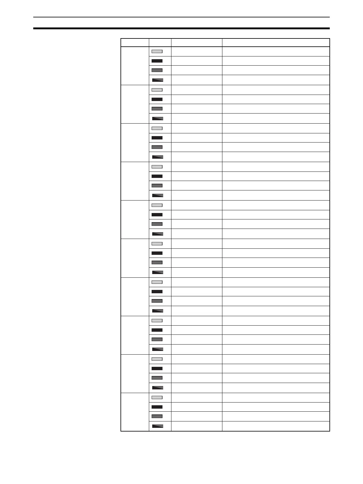
3-A Lit yellow. Input 4 is ON.
Not lit. Input 4 is OFF.
Lit red. Connector 3 is short-circuited.
Flashing red. Connector 3 is disconnected.
3-B Lit yellow. Input 5 is ON.
Not lit. Input 5 is OFF.
Lit red. ---
Flashing red. ---
4-A Lit yellow. Input 6 is ON.
Not lit. Input 6 is OFF.
Lit red. Connector 4 is short-circuited.
Flashing red. Connector 4 is disconnected.
4-B Lit yellow. Input 7 is ON.
Not lit. Input 7 is OFF.
Lit red. ---
Flashing red. ---
5-A Lit yellow. Input 8 is ON.
Not lit. Input 8 is OFF.
Lit red. Connector 5 is short-circuited.
Flashing red. Connector 5 is disconnected.
5-B Lit yellow. Input 9 is ON.
Not lit. Input 9 is OFF.
Lit red. ---
Flashing red. ---
6-A Lit yellow. Input 10 is ON.
Not lit. Input 10 is OFF.
Lit red. Connector 6 is short-circuited.
Flashing red. Connector 6 is disconnected.
6-B Lit yellow. Input 11 is ON.
Not lit. Input 11 is OFF.
Lit red. ---
Flashing red. ---
7-A Lit yellow. Input 12 is ON.
Not lit. Input 12 is OFF.
Lit red. Connector 7 is short-circuited.
Flashing red. Connector 7 is disconnected.
7-B Lit yellow. Input 13 is ON.
Not lit. Input 13 is OFF.
Lit red. ---
Flashing red. ---
Indicator Color Status Meaning (main error)
 Loading...


