63
Environment-resistive Slave Units Section 5-2
(4) Communications Indicators: MS and NS
These indicators show the Unit communications status and network commu-
nications status.
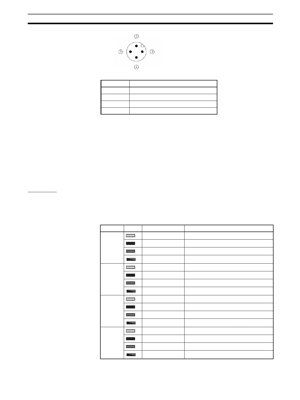
(5) Input Connectors
The input devices are connected to these connectors.
(6) Input Indicators
These indicators show the ON/OFF status of the inputs and the error status of
connected devices.
Indicators
Communications
Indicators
Refer to 3-1-3 Communications Indicators.
Input Indicators These indicators show the ON/OFF status of the inputs and the error status of
connected devices.
Pin Signal
1 V+ (24 V: for internal circuits and inputs)
2NC
3V− (0 V: for internal circuits and inputs)
4NC
Indicator Color Status Meaning (main error)
1-A Lit yellow. Input 0 is ON.
Not lit. Input 0 is OFF.
Lit red. Connector 1 is short-circuited.
Flashing red. Connector 1 is disconnected.
1-B Lit yellow. Input 1 is ON.
Not lit. Input 1 is OFF.
Lit red. ---
Flashing red. ---
2-A Lit yellow. Input 2 is ON.
Not lit. Input 2 is OFF.
Lit red. Connector 2 is short-circuited.
Flashing red. Connector 2 is disconnected.
2-B Lit yellow. Input 3 is ON.
Not lit. Input 3 is OFF.
Lit red. ---
Flashing red. ---
 Loading...


