68
Environment-resistive Slave Units Section 5-2
(4) Communications Indicators: MS and NS
These indicators show the Unit communications status and network commu-
nications status.
(5) Output Power Indicator
This indicator shows the status of the output power supply.
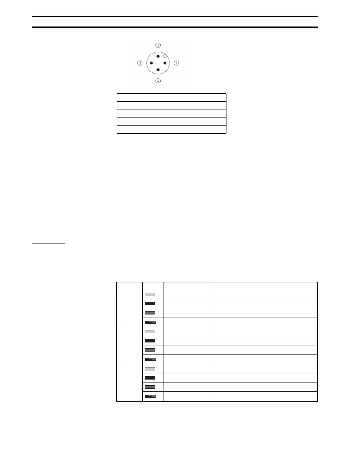
(6) Output Connectors
The output devices are connected to these connectors.
(7) Output Indicators
These indicators show the ON/OFF status of the outputs and the error status
of connected devices.
Indicators
Communications
Indicators
Refer to 3-1-3 Communications Indicators.
Output Indicators These indicators show the ON/OFF status of the outputs and the error status
of connected devices.
Pin Signal
1 V+ (24 V: for internal circuits)
2 24 V (for outputs)
3V− (0 V: for internal circuits)
4 0 V (for outputs)
Indicator Color Status Meaning (main error)
1-A Lit yellow. Output 0 is ON.
Not lit. Output 0 is OFF.
Lit red. Output 0 is short-circuited.
Flashing red. Output 0 is disconnected.
1-B Lit yellow. Output 1 is ON.
Not lit. Output 1 is OFF.
Lit red. Output 1 is short-circuited.
Flashing red. Output 1 is disconnected.
2-A Lit yellow. Output 2 is ON.
Not lit. Output 2 is OFF.
Lit red. Output 2 is short-circuited.
Flashing red. Output 2 is disconnected.
 Loading...


