70
Environment-resistive Slave Units Section 5-2
Output Power Indicator This indicator shows the status of the output power supply.
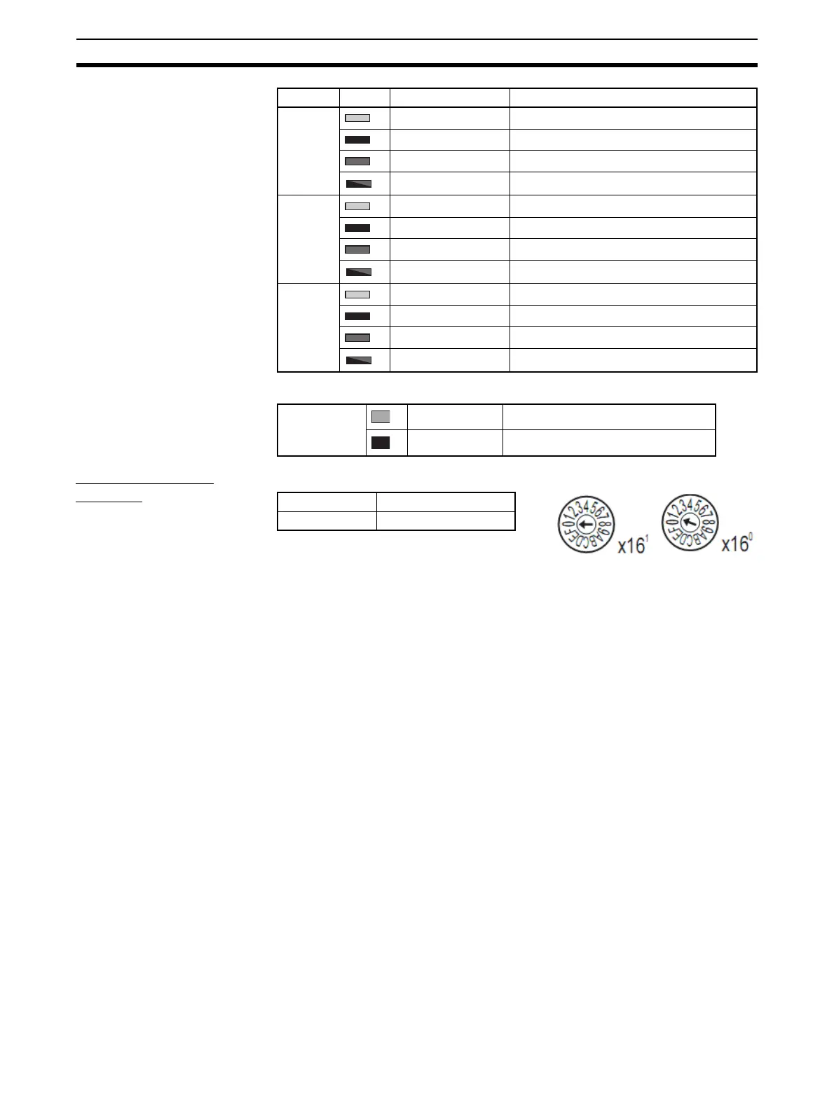
Setting the Node
Address
The rotary switches are used to set the lower digits of the IP address.
Rotary Switch Settings
00 hex: BOOTP or tool setting enabled (factory setting)
01 to FE hex: Setting on rotary switches is lower 8 bits of IP address. (De-
fault setting of upper 24 bits: 192.168.250.)
FF hex: Restores default setting.
(To restore the default setting, set the switches to FF hex, cycle the power
supply, and then set the switches to 00 hex.)
7-B Lit yellow. Output 13 is ON.
Not lit. Output 13 is OFF.
Lit red. Output 13 is short-circuited.
Flashing red. Output 13 is disconnected.
8-A Lit yellow. Output 14 is ON.
Not lit. Output 14 is OFF.
Lit red. Output 14 is short-circuited.
Flashing red. Output 14 is disconnected.
8-B Lit yellow. Output 15 is ON.
Not lit. Output 15 is OFF.
Lit red. Output 15 is short-circuited.
Flashing red. Output 15 is disconnected.
Indicator Color Status Meaning (main error)
AUX (exter-
nal power
supply)
Lit green. Output power is being supplied.
Not lit. Output power is not being supplied.
Setting method Two hexadecimal digits
Setting range 01 to FE
 Loading...


