Controlling Operation and Outputting Data with PLC Link Communications
FQ2-S/CH User’s Manual
for Communications Settings
121
3
Controlling Operation and Outputting Data with an
Ethernet Connection
3-2
Controlling Operation and Outputting Data with PLC Link Communications
This section explains how to configure the communication settings that are required for communication
between the sensor and external devices by PLC Link. Communication specifications (PLC I/O memory area
used for PLC Link communication and types of communication commands) are also described, and a
communication timing chart is provided.
Communications Processing Flow
You can use a PLC Link to communicate between the PLC and the Vision Sensor to perform control via
command/response communications or to output data after measurements. You can use these
communications methods simultaneously.
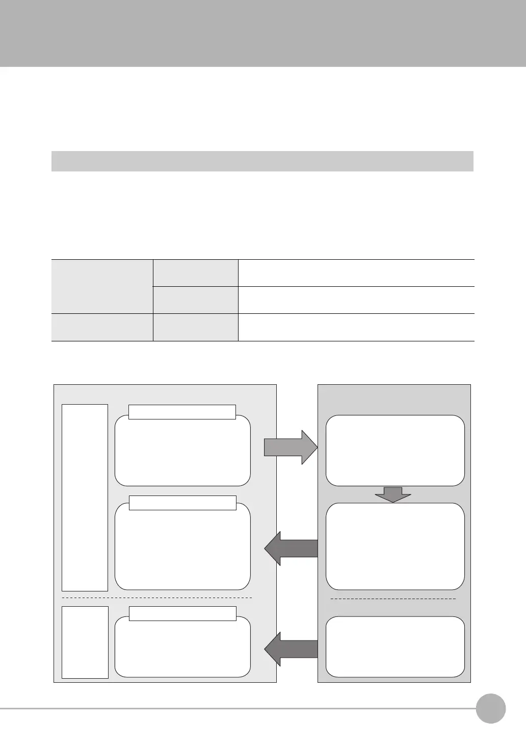
For PLC Link communications, the following three communications areas are set in the PLC to perform
communications.
You can set the area and address settings in the communications specifications of the Vision Sensor to assign
the above three communications areas in the I/O memory of the PLC.
Command/response
communications
1. Command area
This is the area to which you write control commands for the
Vision Sensor to execute.
2. Response area
This is the area to which the Vision Sensor writes the results of
control commands executed from the Command Area.
Data output after mea-
surements
3. Output area
This is the area to which the Vision Sensor writes output data for
measurements after an inspection is performed.
Command area
The following control commands are
written to the Vision Sensor.
●
Control signals
●
Command code
●
Command parameters
Response area
The execution results from the
Vision Sensor are written here.
PLC (master)
Output area
Output data from the Vision Sensor
is written here.
Vision Sensor (slave)
Command
Response
Measurement results are written to
the Response Area of the PLC.
●
Vision Status Flags
●
Command code
●
Response code
●
Response data
●
Output data 0 to 31
●
Character string to output
Execution
After measurements
Measurement results are written to the
Output Area.
Command/
response
communi-
cations
The control commands written to the
Command Area are executed.
Data output
after
measure-
ments
FQ2-S_CH_comm.book 121 ページ 2014年6月26日 木曜日 午前11時47分

 Loading...


