Communicating with an External Device
10
FQ2-S/CH User’s Manual
for Communications Settings
1-2 Communicating with an External Device
FQ2-S3 FQ2-S4
This section gives the communications specifications, describes the control methods that you can use for
communications, and describes the settings that are required before starting communications with an external
device.
Basic Control Operations of the Sensor
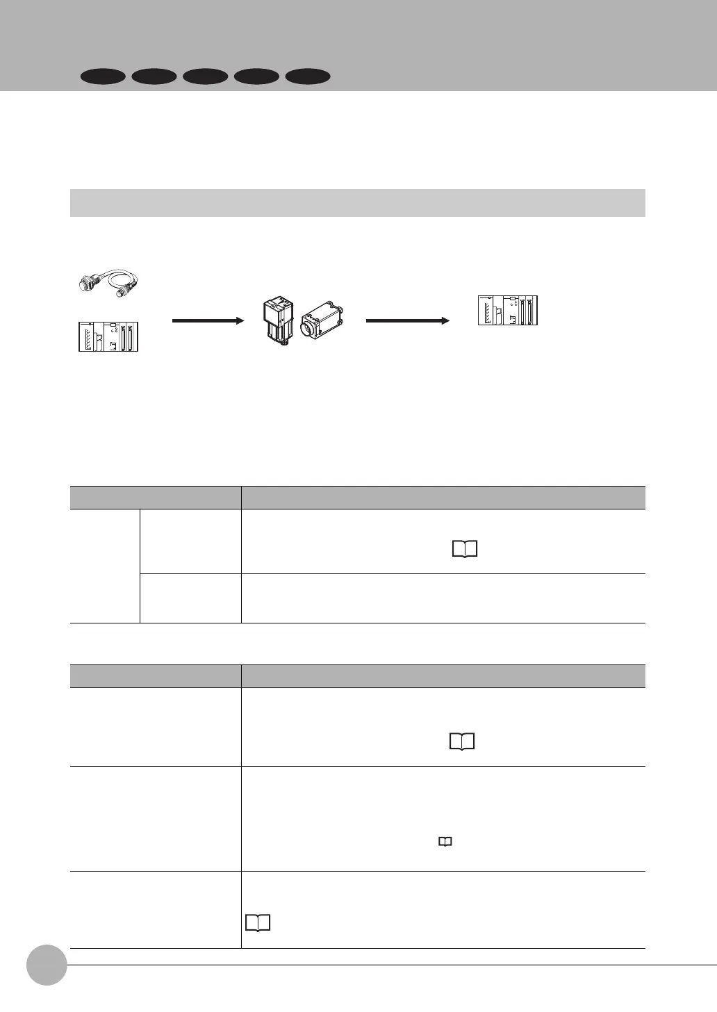
The following figure shows basic communications between an external device and the Sensor and the flow of
signals and data.
The following methods can be used to exchange data between an external device and the Sensor.
Commands That Can Be Input to the Sensor from an External Device
Data Output to an External Device from the Sensor
Ty pe Description
Control com-
mands
Control signals
(input signals)
A measurement is executed when a measurement trigger (i.e., an ON TRIG sig-
nal) is input.
For information on control signals, refer to Control with Control Signals and
Status Signals: p.18.
Communications
command input
Various commands can be executed, such as measuring commands and scene
change. The communications commands depend on the communications proto-
col that you use. Refer to the section for each communications protocol for details.
Ty p e Description
Status signals When the Sensor confirms a control signal or communications command input
and begins measurement processing, the status of the Sensor is reported to the
external device through status signals (e.g., a BUSY signal).
For information on status signals, refer to Control with Control Signals and
Status Signals: p.18.
Overall judgement NG is output whenever there is one or more NGs in the judgement results for mul-
tiple inspection items.
*1
The overall judgement can be output through the OR signal or through the JG out-
put parameter.
*1: This behavior can be changed in the settings.
For information on the OR signal, refer to Control with Control Signals and Status Sig-
nals: p.18.
For information on the JG output parameter.
Measured values The measured values from inspection items can be output. The output items must
be inspection items for output and registered as output data (data 0 to data 31).
Refer to the following for details.
Settings Required for Data Output: p.61, 97, 124, 148, 169, 198.
You can also use commands to obtain results after a measurement is performed.
Trigger sensor
PLC
PLC
The measurement
results are output.
• Status signals
• Overall judgement
• Measured values
• Character strings
Measurement
triggers and other
control commands
are input.
Sensor
FQ2-S_CH_comm.book 10 ページ 2014年6月26日 木曜日 午前11時47分
 Loading...


