Confirming the System Configuration
8
FQ2-S/CH User’s Manual
for Communications Settings
1-1 Confirming the System Configuration
FQ2-S3 FQ2-S4
The FQ2-S/CH series is Vision System that perform measurement processing through measurement objects
that are imaged by a Camera.
In a system configuration that is connected to a PLC, computer, or other external device, measurement
commands can be received from and measurement results can be output to the external device.
FQ2-S/CH Series System Configuration
The following types of system configurations can be used with the FQ2.
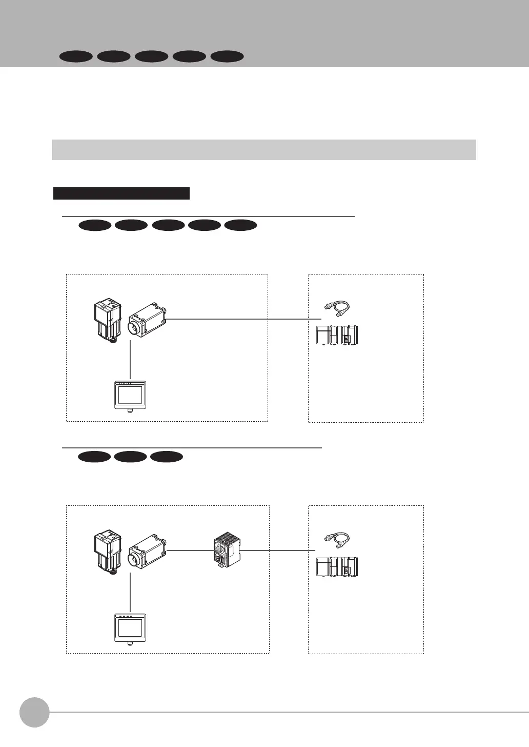
Parallel Interface Connection
Sensor Data
Unit cable
Parallel Interface
Sensor Data Unit
I/O cable
Basic configuration External devices
Setup Tool
(Touch Finder or PC Tool)
Special Ethernet Cable
(RJ45/M12)
Connection with Standard Parallel Interface of the Vision Sensor
I/O control PLC
I/O cable
Basic configuration
FQ2-S/CH Series
FQ2-S/CH Series
External devices
Trigger sensor
I/O control PLC
Trigger sensor
Setup Tool
(Touch Finder or PC Tool)
Special Ethernet Cable
(RJ45/M12)
A Parallel Interface Sensor Data Unit can be installed to enable output of measured values,
parameters, calculation results, and other information.
Use an I/O cable for input of measurement triggers and communication commands,
and for output of OK/NG judgement results.
Connection through a Parallel Interface Sensor Data Unit
FQ2-S1
FQ2-S3 FQ2-S4 FQ2-CH
FQ2-S3 FQ2-S4 FQ2-CH
FQ2-S2
FQ2-S_CH_comm.book 8 ページ 2014年6月26日 木曜日 午前11時47分
 Loading...


