Controlling Operation and Outputting Data with PLC Link Communications
FQ2-S/CH User’s Manual
for Communications Settings
123
3
Controlling Operation and Outputting Data with an
Ethernet Connection
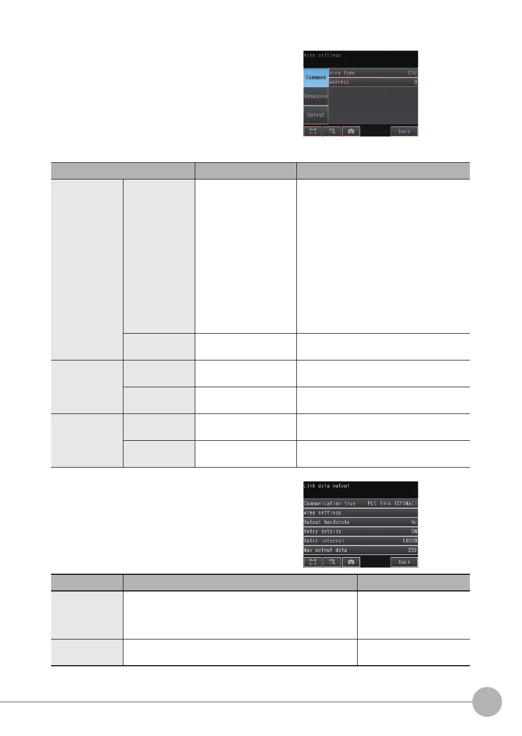
3 Press [Area settings].
Here, you specify the addresses in the I/O memory of
the PLC that are to be allocated as the communica-
tions areas for PLC Link communications.
Press [Command], [Response], and [Output] and set
the memory area ([Area type]) and first word ([Ad-
dress]) in the I/O memory of the PLC to allocate to
each of these communications areas. When you are
finished, press [Back].
Item
Description Setting range
Command (com-
mand area)
Area type Select the area for the
Command Area in the
PLC.
If PLC Link (SYSMAC) is selected:
CIO Area (CIO)
Work Area (WR)
Holding Bit Area (HR)
Auxiliary Bit Area (AR)
DM Area (DM)
EM Area (EM0 to EMC)
Default: CIO Area (CIO)
If PLC Link (MELSEC) is selected:
Data Register (Data registers)
File Register (File registers)
Link Register (Link registers)
Default: Data Register
Address
Set the first address of the
command area in the PLC.
0 to 99,999
Default: 0
Response
(response area)
Area type
Set the PLC memory area
for the response area.
Same as for the Command Area.
Address
Set the first address of the
response area in the PLC.
0 to 99,999
Default: 100
Output (output
area)
Area type
Set the PLC memory area
for the output area.
Same as for the Command Area.
Address
Set the first address of the
output area in the PLC.
0 to 99,999
Default: 200
4 Set the communications protocol ([Comm. type]) to
PLC Link communications.
Item
Description Setting range
Output handshake Enables or disables handshaking.
• Yes: Data is output when the DSA signal from the PLC turns
ON.
• No: Data is output regardless of the signal state from the PLC.
No or Yes
Default: No
Retry details Enables or disables retrying communications. ON or OFF
Default: ON
FQ2-S_CH_comm.book 123 ページ 2014年6月26日 木曜日 午前11時47分

 Loading...


