Controlling Operation and Outputting Data with the Sensor's Standard Parallel Connection
FQ2-S/CH User’s Manual
for Communications Settings
45
2
Controlling Operation and Outputting Data with a Par-
allel Connection
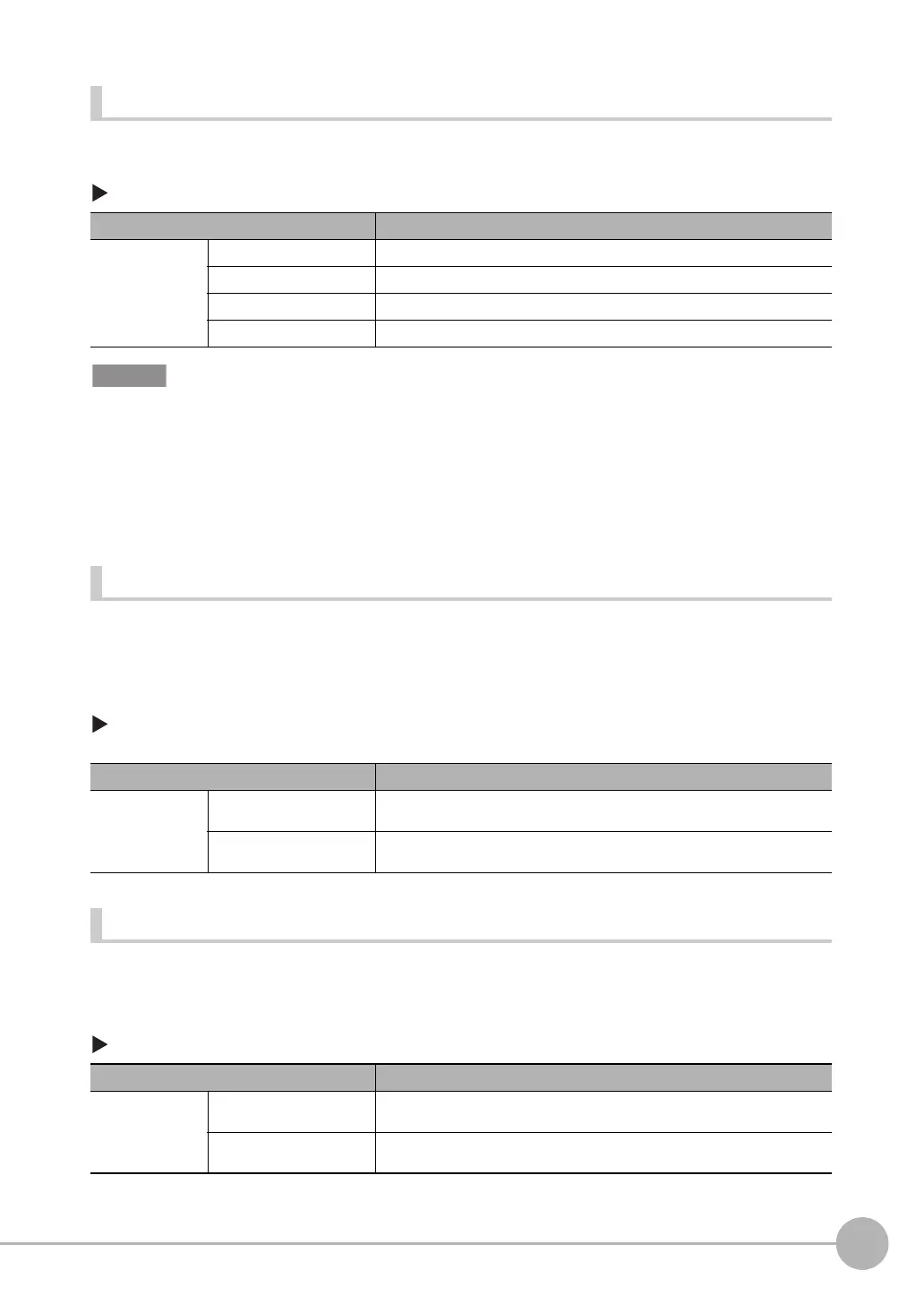
Adjusting the End Timing of the BUSY Signal
The end timing of the BUSY signal can be changed.
[In/Out] − [I/O setting] − [I/O setting] − [Output] Tab Page − [BUSY output]
Do not disconnect the Ethernet cable between the Sensor and the Touch Finder if the Sensor and Touch Finder are
connected through an Ethernet switch and the BUSY output condition is set to [Data logging], [Image logging], or
[Result display].
The Sensor will wait for the Touch Finder to answer, and the results and measurement time will be affected.
To disconnect the Sensor and Touch Finder during measurements in the above situation, clear the selection of the
Sensor from the list of Sensors on the Touch Finder before you disconnect the cable.
Changing the Polarity of the Output Signals
You can change the polarity of the output signals that are assigned to OUT0 to OUT3 (regardless of what
signal is assigned to the output).
Settings
[In/Out] − [I/O setting] − [I/O setting] − [Output] − [OUT0 Polarity], [OUT1 Polarity] or [OUT2
Polarity]
Changing the Types of Commands That Can Be Used
You can select the types of commands used in IN0 to IN5.
Settings
[In/Out] − [I/O setting] − [I/O setting] − [Input] − [Input mode]
Item Description
BUSY output Measurement (default) The BUSY signal turns OFF when the measurement is completed.
Data logging The BUSY signal turns OFF when data logging is completed.
Image logging The BUSY signal turns OFF when image logging is completed.
Result display The BUSY signal turns OFF when the result display is completed.
Item Description
OUT0 Polarity,
OUT1 Polarity, or
OUT2 Polarity
Positive (default) The output signal that is assigned to OUT0 to OUT3 is turned ON when the Sen-
sor is executing a process.
Negative The output signal that is assigned to OUT0 to OUT3 is turned ON when the Sen-
sor can receive the trigger.
Item Description
Input mode Standard mode (default) IN0 to IN4 are only used for line process changes.
A maximum of 32 scenes are selectable.
Expanded mode Enables use of IN0 to IN4 for commands other than line process changes.
A maximum of 16 scenes are selectable.
FQ2-S_CH_comm.book 45 ページ 2014年6月26日 木曜日 午前11時47分

 Loading...


